Machine Vision Systems for Industrial Quality Control Inspections
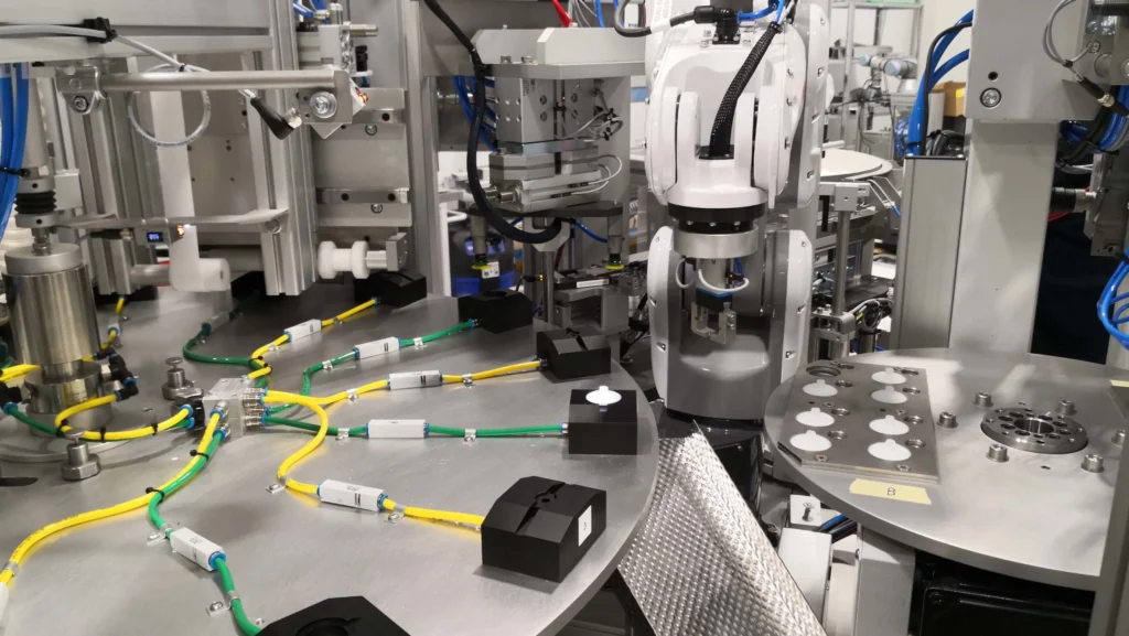
Machine vision systems for industrial quality control inspections are automated systems that use cameras and image processing software to inspect products for defects. They can be used to inspect products at any stage of the manufacturing process, from raw materials to finished products.
Machine vision systems offer a number of advantages over traditional inspection methods, including:
Increased accuracy: Machine vision systems can inspect products with a higher degree of accuracy than human inspectors. This is because the systems can be programmed to identify and classify defects that are too difficult or time-consuming for humans to see.
Reduced costs: Machine vision systems can help to reduce the costs associated with quality control by eliminating the need for manual inspection. This can free up workers to perform other tasks or to focus on quality control in other areas.
Increased productivity: Machine vision systems can help to increase productivity by reducing the time required to inspect products. This is because the systems can inspect products very quickly and accurately.
Improved quality: Machine vision systems can help to improve the quality of products by identifying and eliminating defects early in the manufacturing process. This can help to reduce the number of defective products that reach customers.
Machine vision systems are used in a wide variety of industries, including automotive, electronics, food and beverage, and consumer goods. They are used to inspect a wide variety of products, such as:
Automotive parts: engine blocks, transmissions, axles, etc.
Electronic components: circuit boards, semiconductors, etc.
Food and beverage products: bottles, cans, bags, etc.
Consumer goods: toys, appliances, furniture, etc.
Here are some examples of how machine vision systems are used for industrial quality control inspections:
In the automotive industry, machine vision systems are used to inspect car doors, hoods, and fenders for defects such as scratches, dents, and misaligned parts.
In the electronics industry, machine vision systems are used to inspect circuit boards for defects such as missing components, solder bridges, and cracks.
In the food and beverage industry, machine vision systems are used to inspect bottles and cans for defects such as cracks, dents, and foreign objects.
In the consumer goods industry, machine vision systems are used to inspect toys, appliances, and furniture for defects such as missing parts, cracks, and scratches.
Machine vision systems are an essential tool for businesses that need to produce high-quality products. They can help to improve accuracy, reduce costs, increase productivity, and improve quality.
Here are some of the latest trends in machine vision systems for industrial quality control inspections:
The use of deep learning: Deep learning is a type of machine learning that uses artificial neural networks to learn from data. Deep learning is being used to develop machine vision systems that can identify and classify defects with even greater accuracy than traditional systems.
The use of 3D imaging: 3D imaging is being used to develop machine vision systems that can inspect products from all angles. This can help to identify defects that would be difficult or impossible to see with traditional 2D imaging.
The use of edge computing: Edge computing is a type of computing architecture in which data is processed and analyzed at the point of collection. This can help to reduce latency and improve performance in machine vision systems.
Machine vision systems for industrial quality control inspections are a rapidly evolving field. New technologies and applications are being developed all the time. Machine vision systems are playing an increasingly important role in helping businesses to produce high-quality products.
The Use of Deep Learning
Deep learning is a subset of machine learning that has gained significant prominence in various industries, including manufacturing and metalworking. It has the capability to process and analyze vast amounts of data to make complex decisions, and it has been applied in several ways within these sectors:
Defect Detection and Quality Control: Deep learning models can be trained to identify defects in metal components or products by analyzing images or sensor data. This is particularly useful in ensuring the quality and consistency of manufactured parts.
Predictive Maintenance: Deep learning can be used to predict when equipment or machinery is likely to fail based on data from sensors and historical maintenance records. This allows for proactive maintenance to reduce downtime and increase efficiency.
Process Optimization: Deep learning algorithms can analyze data from various manufacturing processes, such as CNC machining or 3D printing, to optimize parameters and improve the overall process efficiency.
Robotics and Automation: Deep learning is applied in robot vision and control systems to enable robots to perform tasks like picking and placing objects, welding, and assembly with greater precision and autonomy.
Supply Chain and Inventory Management: Deep learning can be used to optimize supply chain operations, predict demand, and manage inventory more efficiently, reducing excess stock and associated costs.
Resource Allocation: Deep learning can help allocate resources, such as energy, raw materials, and labor, more effectively by analyzing historical data and real-time information.
Anomaly Detection: Deep learning models are used to detect unusual patterns or deviations in manufacturing processes that may indicate defects, equipment malfunctions, or safety issues.
Process Control and Optimization: Deep learning models can control and optimize complex manufacturing processes in real time, making adjustments to variables to ensure product quality and consistency.
Customized Product Manufacturing: Deep learning can be used to customize manufacturing processes to produce products tailored to individual customer requirements.
Energy Efficiency: Deep learning models can optimize energy usage within manufacturing facilities, reducing energy costs and environmental impact.
Pattern Recognition: Deep learning can recognize complex patterns in data, which is useful for tasks like identifying the optimal parameters for a particular manufacturing process.
Waste Reduction: By analyzing data from various stages of production, deep learning can help identify areas where waste can be reduced, improving resource efficiency and sustainability.
Document Processing: In administrative and compliance tasks, deep learning is employed to process and classify documents, contracts, and invoices, streamlining record-keeping and ensuring compliance.
Deep learning models, such as convolutional neural networks (CNNs), recurrent neural networks (RNNs), and transformers, have demonstrated impressive capabilities in handling complex, unstructured data in the manufacturing and metalworking sectors. These models require substantial computational resources and a large volume of labeled data for training, but they can lead to substantial improvements in efficiency, quality, and cost savings in various manufacturing processes.
The Use of 3D Imaging
3D imaging technologies play a crucial role in various aspects of metalworking and manufacturing. They enable the creation, inspection, and analysis of 3D representations of objects and environments. Here are some of the key uses of 3D imaging in these industries:
3D Printing and Additive Manufacturing: 3D imaging is fundamental for 3D printing and additive manufacturing processes. It is used to create 3D models of parts and components, which are then printed layer by layer. 3D scanners can also capture existing objects for replication or reverse engineering.
Quality Control and Inspection: 3D imaging systems, such as laser scanners or structured light scanners, can quickly and accurately inspect the dimensions and surfaces of manufactured parts. They are particularly useful for complex geometries that are difficult to measure with traditional methods.
Dimensional Analysis: 3D imaging can provide precise measurements of the dimensions and tolerances of metal parts, helping to ensure they meet design specifications.
Defect Detection: 3D imaging technologies can identify defects and imperfections on the surface of metal components, such as cracks, scratches, and irregularities, which are often challenging to detect with 2D methods.
Reverse Engineering: 3D scanning and imaging allow for the reverse engineering of existing metal parts or objects. This is valuable for replicating or modifying legacy components.
Tool Path Planning: 3D imaging is used in computer-aided manufacturing (CAM) to plan tool paths for CNC machining, ensuring optimal material removal and part accuracy.
Mold and Die Design: 3D imaging aids in the design and inspection of molds and dies for metal casting and forming processes.
Digital Twins: 3D imaging data can be used to create digital twins of physical manufacturing equipment and processes, allowing for real-time monitoring and optimization.
Robotics and Automation: 3D imaging is used for robot guidance and object recognition, enabling robots to manipulate and assemble metal components with precision.
Assembly Verification: 3D imaging can be used to verify that components are assembled correctly, ensuring that products meet quality standards.
Welding and Fabrication: 3D imaging helps in the positioning and tracking of welding torches, ensuring accurate welds in metal fabrication.
Non-Destructive Testing (NDT): 3D imaging methods, like computed tomography (CT) and digital radiography, are used for NDT of metal components, providing internal inspection without damaging the material.
Tool Wear Analysis: 3D imaging can be used to monitor and analyze tool wear in metalworking processes, optimizing tool replacement schedules.
Surface Finish Assessment: 3D imaging can assess the surface finish of metal parts, ensuring they meet quality standards.
Virtual Reality (VR) and Augmented Reality (AR): 3D imaging data can be integrated into VR and AR applications for training, maintenance, and visualization of manufacturing processes.
3D imaging technologies, such as laser scanning, structured light scanning, and photogrammetry, have become indispensable in improving the efficiency, accuracy, and quality of metalworking and manufacturing processes. They enable engineers and manufacturers to work with complex geometries, ensure product quality, and optimize production workflows.
The Use of Edge Computing
Edge computing is increasingly being utilized in the manufacturing and metalworking industries to process data closer to the source, rather than sending it to centralized cloud servers. This approach offers several advantages, including reduced latency, improved data security, and the ability to make real-time decisions. Here are some key applications of edge computing in these sectors:
Real-time Process Control: Edge computing enables real-time control and monitoring of manufacturing processes. Data from sensors and equipment is processed locally, allowing for immediate adjustments and optimizations without the delay of sending data to remote servers.
Quality Control: Edge computing can perform real-time quality control by analyzing sensor data to detect defects or irregularities in products as they are being manufactured. This ensures that only high-quality products are produced.
Predictive Maintenance: Edge computing is used for predictive maintenance by analyzing data from sensors embedded in machinery. It can detect signs of equipment wear or imminent failures, allowing for proactive maintenance and minimizing downtime.
Robotics and Automation: Edge computing is essential for real-time robot control and decision-making. Robots can adapt to changes in their environment or respond to new instructions without relying on a distant cloud server.
Local Data Storage: Edge devices can store and manage data locally, which is especially important for manufacturing operations with intermittent or unreliable network connectivity. Data can be temporarily stored and then synchronized with central systems when a connection is available.
Security and Compliance: Edge computing can enhance data security by keeping sensitive data within the factory’s network. This is important for protecting intellectual property and complying with data privacy regulations.
Energy Efficiency: Edge computing can optimize the use of energy in manufacturing processes by monitoring and controlling equipment based on real-time demand and environmental conditions.
Environmental Monitoring: Edge devices can monitor environmental factors, such as temperature, humidity, and air quality, within manufacturing facilities to ensure optimal working conditions and compliance with environmental regulations.
Supply Chain Visibility: Edge computing can be used to track and manage inventory and shipments at a local level, improving supply chain efficiency and reducing lead times.
Local Decision-Making: Edge devices can make critical decisions locally, such as sorting products on a conveyor belt, adjusting machine settings, or flagging anomalies without the need for centralized control.
Customization and Personalization: Edge computing allows for real-time customization of products, such as engraving or labeling, based on individual customer preferences.
Remote Assistance: Edge devices can support remote maintenance and troubleshooting by providing real-time data and visual information to off-site experts.
Data Aggregation: While edge devices process data locally, they can also aggregate summarized data for trend analysis and performance monitoring at a higher level.
Edge computing technologies, including edge servers, gateways, and IoT devices, are becoming integral to modern manufacturing and metalworking operations. They help companies improve efficiency, reduce operational costs, and enhance responsiveness to changes in production environments.
Quality control vision systems are used to inspect products for defects. They use cameras and image processing software to identify and classify defects. Quality control vision systems can be used to inspect products at any stage of the manufacturing process, from raw materials to finished products.
Quality control vision systems offer a number of benefits, including:
Increased accuracy: Quality control vision systems can inspect products with a higher degree of accuracy than human inspectors. This is because the systems can be programmed to identify and classify defects that are too difficult or time-consuming for humans to see.
Reduced costs: Quality control vision systems can help to reduce the costs associated with quality control by eliminating the need for manual inspection. This can free up workers to perform other tasks or to focus on quality control in other areas.
Increased productivity: Quality control vision systems can help to increase productivity by reducing the time required to inspect products. This is because the systems can inspect products very quickly and accurately.
Improved quality: Quality control vision systems can help to improve the quality of products by identifying and eliminating defects early in the manufacturing process. This can help to reduce the number of defective products that reach customers.
Quality control vision systems are used in a wide variety of industries, including automotive, electronics, food and beverage, and consumer goods. They are used to inspect a wide variety of products, including:
Automotive parts: engine blocks, transmissions, axles, etc.
Electronic components: circuit boards, semiconductors, etc.
Food and beverage products: bottles, cans, bags, etc.
Consumer goods: toys, appliances, furniture, etc.
Quality control vision systems are an essential tool for businesses that need to produce high-quality products. They can help to improve accuracy, reduce costs, increase productivity, and improve quality.
Here are some examples of how quality control vision systems are used in industry:
In the automotive industry, quality control vision systems are used to inspect car doors, hoods, and fenders for defects.
In the electronics industry, quality control vision systems are used to inspect circuit boards for defects.
In the food and beverage industry, quality control vision systems are used to inspect bottles and cans for defects.
In the consumer goods industry, quality control vision systems are used to inspect toys, appliances, and furniture for defects.
Overall, quality control vision systems are a valuable asset for businesses that need to inspect products quickly, accurately, and cost-effectively.
Quality Control Vision Systems Application Areas
Quality Control Vision Systems Application Areas
Quality control vision systems are used in a wide range of industries to inspect products for defects and ensure that they meet quality standards. Here are some of the most common application areas:
Food and beverage: Vision systems are used to inspect food and beverage products for defects such as foreign objects, underfilled containers, and incorrect labeling.
Pharmaceutical: Vision systems are used to inspect pharmaceutical products for defects such as broken tablets, missing capsules, and incorrect labeling.
Automotive: Vision systems are used to inspect automotive parts for defects such as cracks, scratches, and incorrect dimensions.
Electronics: Vision systems are used to inspect electronic components for defects such as missing components, incorrect soldering, and damaged circuit boards.
Metalworking: Vision systems are used to inspect metal parts for defects such as cracks, voids, and incorrect dimensions.
Packaging: Vision systems are used to inspect packaged products for defects such as incorrect labeling, damaged packaging, and missing products.
In addition to these general application areas, quality control vision systems are also used in a variety of other industries, such as aerospace, medical devices, and printing.
Here are some specific examples of how quality control vision systems are used in different industries:
Food and beverage: Vision systems can be used to inspect fruits and vegetables for ripeness and defects, to detect foreign objects in food products, and to ensure that food products are packaged correctly.
Pharmaceutical: Vision systems can be used to inspect pharmaceutical tablets and capsules for defects, to ensure that they are filled correctly, and to verify that they are labeled correctly.
Automotive: Vision systems can be used to inspect car bodies for defects, to ensure that headlights and taillights are aligned correctly, and to verify that VIN numbers are correct.
Electronics: Vision systems can be used to inspect circuit boards for defects, to ensure that components are placed correctly, and to verify that solder joints are sound.
Metalworking: Vision systems can be used to inspect metal castings and forgings for defects, to ensure that they are machined to the correct dimensions, and to verify that they are heat treated correctly.
Packaging: Vision systems can be used to inspect packaged products for defects, to ensure that they are labeled correctly, and to verify that they are packaged in the correct boxes or cases.
Quality control vision systems are an essential tool for many industries. They help to ensure that products are of high quality and that they meet customer expectations.
Food and Beverage
Quality control vision systems are used in the food and beverage industry to inspect products for a variety of defects, including:
Foreign objects: Vision systems can be used to detect foreign objects such as insects, pieces of glass, and metal shavings in food products.
Underfilled containers: Vision systems can be used to ensure that food and beverage containers are filled to the correct level.
Incorrect labeling: Vision systems can be used to verify that food and beverage products are labeled correctly with the correct product name, ingredients, and nutritional information.
Vision systems can also be used to inspect food and beverage products for more subtle defects, such as ripeness and color. For example, vision systems can be used to identify fruits and vegetables that are ripe and ready to be picked, or to detect blemishes on food products.
Quality control vision systems are an essential tool for the food and beverage industry. They help to ensure that food products are safe and of high quality, and that they meet customer expectations.
Here are some specific examples of how quality control vision systems are used in the food and beverage industry:
Fruits and vegetables: Vision systems can be used to inspect fruits and vegetables for ripeness and defects, such as bruises, blemishes, and pests. This helps to ensure that only high-quality fruits and vegetables are packaged and sold.
Meat and poultry: Vision systems can be used to inspect meat and poultry for defects such as bone fragments, bruises, and discoloration. This helps to ensure that only safe and wholesome meat and poultry products are sold.
Dairy products: Vision systems can be used to inspect dairy products for defects such as curdled milk, foreign objects, and incorrect labeling. This helps to ensure that only high-quality dairy products are sold.
Packaged foods: Vision systems can be used to inspect packaged foods for defects such as incorrect labeling, damaged packaging, and missing products. This helps to ensure that packaged foods meet customer expectations.
Quality control vision systems are a valuable tool for the food and beverage industry. They help to ensure that food products are safe, of high quality, and meet customer expectations.
Pharmaceutical
Quality control vision systems are used in the pharmaceutical industry to inspect products for a variety of defects, including:
Broken tablets: Vision systems can be used to detect broken tablets in pharmaceutical packaging.
Missing capsules: Vision systems can be used to detect missing capsules in pharmaceutical packaging.
Incorrectly filled capsules: Vision systems can be used to detect capsules that are not filled correctly.
Incorrect labeling: Vision systems can be used to verify that pharmaceutical products are labeled correctly with the correct product name, dosage, and expiration date.
Vision systems can also be used to inspect pharmaceutical products for more subtle defects, such as the presence of impurities. For example, vision systems can be used to detect the presence of foreign particles in pharmaceutical liquids, or to detect the presence of air bubbles in pharmaceutical suspensions.
Quality control vision systems are an essential tool for the pharmaceutical industry. They help to ensure that pharmaceutical products are safe and of high quality, and that they meet regulatory requirements.
Here are some specific examples of how quality control vision systems are used in the pharmaceutical industry:
Tablets: Vision systems can be used to inspect pharmaceutical tablets for defects such as cracks, chips, and incorrect dimensions. This helps to ensure that only high-quality tablets are packaged and sold.
Capsules: Vision systems can be used to inspect pharmaceutical capsules for defects such as breaks, holes, and incorrect filling. This helps to ensure that only high-quality capsules are packaged and sold.
Liquids: Vision systems can be used to inspect pharmaceutical liquids for defects such as cloudiness, sediment, and foreign particles. This helps to ensure that only high-quality liquids are packaged and sold.
Suspensions: Vision systems can be used to inspect pharmaceutical suspensions for defects such as air bubbles, settling, and foreign particles. This helps to ensure that only high-quality suspensions are packaged and sold.
Quality control vision systems are a valuable tool for the pharmaceutical industry. They help to ensure that pharmaceutical products are safe, of high quality, and meet regulatory requirements.
Automotive
Quality control vision systems are used in the automotive industry to inspect products for a variety of defects, including:
Cracks: Vision systems can be used to detect cracks in car bodies, windshields, and other automotive components
Scratches: Vision systems can be used to detect scratches on car bodies, paint, and other automotive components.
Incorrect dimensions: Vision systems can be used to ensure that automotive components are machined to the correct dimensions.
Incorrect alignment: Vision systems can be used to ensure that headlights, taillights, and other automotive components are aligned correctly.
VIN number verification: Vision systems can be used to verify that VIN numbers on automotive components are correct.
Vision systems can also be used to inspect automotive products for more subtle defects, such as the presence of imperfections in the paint or the quality of the welds. For example, vision systems can be used to detect the presence of orange peel in the paint or to detect cracks in the welds.
Quality control vision systems are an essential tool for the automotive industry. They help to ensure that automotive products are safe and of high quality, and that they meet customer expectations.
Here are some specific examples of how quality control vision systems are used in the automotive industry:
Car bodies: Vision systems can be used to inspect car bodies for cracks, scratches, and incorrect dimensions. This helps to ensure that car bodies are safe and of high quality.
Windshields: Vision systems can be used to inspect windshields for cracks, scratches, and other defects. This helps to ensure that windshields are safe and provide good visibility.
Paint: Vision systems can be used to inspect paint for defects such as orange peel, runs, and drips. This helps to ensure that paint jobs are of high quality and meet customer expectations.
Welding: Vision systems can be used to inspect welds for cracks, porosity, and other defects. This helps to ensure that welds are strong and safe.
VIN numbers: Vision systems can be used to verify that VIN numbers on automotive components are correct. This helps to ensure that automotive components can be traced back to the manufacturer in case of a recall.
Quality control vision systems are a valuable tool for the automotive industry. They help to ensure that automotive products are safe, of high quality, and meet customer expectations.
Electronics
Quality control vision systems are used in the electronics industry to inspect products for a variety of defects, including:
Missing components: Vision systems can be used to detect missing components on circuit boards
Incorrectly placed components: Vision systems can be used to detect components that are not placed correctly on circuit boards.
Incorrect soldering: Vision systems can be used to detect solder joints that are not sound.
Damaged components: Vision systems can be used to detect damaged components on circuit boards.
Vision systems can also be used to inspect electronic products for more subtle defects, such as the presence of impurities or the quality of the assembly. For example, vision systems can be used to detect the presence of flux residue on circuit boards or to detect loose solder joints.
Quality control vision systems are an essential tool for the electronics industry. They help to ensure that electronic products are of high quality and meet customer expectations.
Here are some specific examples of how quality control vision systems are used in the electronics industry:
Circuit boards: Vision systems can be used to inspect circuit boards for missing components, incorrectly placed components, incorrect soldering, and damaged components. This helps to ensure that circuit boards are of high quality and meet customer expectations.
Integrated circuits (ICs): Vision systems can be used to inspect ICs for defects such as missing pins, cracks, and incorrect dimensions. This helps to ensure that ICs are of high quality and meet customer expectations.
Semiconductor wafers: Vision systems can be used to inspect semiconductor wafers for defects such as cracks, scratches, and incorrect dimensions. This helps to ensure that semiconductor wafers are of high quality and meet customer expectations.
Electronic assemblies: Vision systems can be used to inspect electronic assemblies for defects such as missing components, incorrectly placed components, incorrect soldering, and damaged components. This helps to ensure that electronic assemblies are of high quality and meet customer expectations.
Quality control vision systems are a valuable tool for the electronics industry. They help to ensure that electronic products are of high quality, meet customer expectations, and are safe to use.
Metalworking
Machine vision, also known as computer vision, plays a significant role in metalworking industries by providing automation, quality control, and process optimization. Machine vision systems use cameras and image processing software to analyze and make decisions based on visual information. In metalworking, machine vision is employed in various ways:
Quality Control and Inspection: Machine vision systems can inspect raw materials, semi-finished products, and finished parts for defects, such as surface imperfections, cracks, and dimensional accuracy. This ensures that only high-quality components move through the manufacturing process.
Defect Detection: By capturing high-resolution images of metal components, machine vision systems can identify defects that are difficult to detect with the human eye. These systems can trigger alarms or reject parts that don’t meet quality standards.
Measurement and Dimensional Control: Machine vision can measure the dimensions of metal parts with high precision, ensuring they meet specifications and tolerances. This is crucial for maintaining product consistency.
Pattern Recognition: Machine vision can identify and sort different metal parts based on their shape, size, or markings. This is particularly useful in picking and sorting applications.
Alignment and Positioning: In metalworking, precise positioning and alignment of components are crucial. Machine vision systems can provide real-time feedback to robotic systems or machine tools to ensure accurate placement and alignment of parts.
Surface Finish Assessment: Machine vision can assess the surface finish of metal parts, identifying issues like roughness or scratches that might affect performance or appearance.
Barcode and Label Reading: Machine vision systems can read barcodes and labels on metal products to track them through the manufacturing process and ensure they are correctly identified and sorted.
Welding Inspection: In metal fabrication, machine vision can be used to inspect weld quality, ensuring that welds are consistent and meet quality standards.
Robotic Guidance: Machine vision is used for guiding robots in tasks such as picking and placing metal components, welding, and assembly. This helps improve the accuracy and efficiency of these processes.
Part Identification and Sorting: Machine vision can identify different types of metal parts and sort them based on predefined criteria, facilitating inventory management and production flow.
Traceability: Machine vision systems can capture images and data related to each metal component produced, creating a record for traceability and quality control.
Real-time Process Monitoring: Machine vision provides real-time feedback on the production process, helping operators detect and address issues as they occur, thereby reducing scrap and rework.
By incorporating machine vision into metalworking processes, manufacturers can achieve higher levels of precision, quality, and efficiency. This technology helps reduce labor costs, improve product consistency, and ensure compliance with quality standards. It is a critical component of modern manufacturing in the metalworking industry, contributing to its competitiveness and sustainability.
Machine Vision in Packaging
Machine vision is widely used in the packaging industry to enhance the efficiency, quality, and safety of packaging processes. It involves the use of cameras, sensors, and image processing software to inspect, monitor, and control various aspects of packaging operations. Here are some key applications of machine vision in packaging:
Quality Inspection: Machine vision systems can inspect packaging materials (e.g., labels, cartons, bottles, and cans) for defects such as cracks, creases, printing errors, or missing labels. This ensures that the final product meets quality standards and looks appealing to consumers.
Print Verification: Machine vision can verify the accuracy and quality of printed information on packaging, such as expiration dates, barcodes, and product labels. This is critical for compliance and traceability.
Seal and Closure Inspection: Machine vision is used to check the seals and closures of packages, ensuring they are properly sealed and secure. This is crucial for maintaining product freshness and preventing tampering.
Fill Level Inspection: In the food and beverage industry, machine vision can verify the fill levels in containers to ensure that customers receive the correct quantity of product.
Label Alignment and Orientation: Machine vision systems can check if labels are correctly applied and oriented on products. Misaligned labels can affect branding and product presentation.
Packaging Line Monitoring: Machine vision can monitor the entire packaging process, detecting jams, misfeeds, and other issues that can disrupt production. This real-time monitoring helps reduce downtime and increase productivity.
Packaging Counting: In applications such as pharmaceuticals or confectionery, machine vision can count and verify the correct number of items in each package.
Color Inspection: Machine vision can be used to ensure that the colors of packaging materials and labels are consistent and meet brand standards.
Barcode and QR Code Reading: Machine vision systems can read barcodes and QR codes for product identification, tracking, and traceability throughout the supply chain.
Container Verification: In the beverage industry, machine vision can verify the type and integrity of bottles, cans, or other containers to ensure they are suitable for packaging.
Package Integrity: Machine vision can inspect the integrity of flexible packaging materials (e.g., pouches, bags) by identifying punctures, wrinkles, or other issues that may compromise the product’s shelf life.
Robot Guidance: Machine vision is used for guiding robotic systems in picking and placing products into packaging, ensuring precise and consistent placement.
Anti-Counterfeiting: Machine vision can help detect counterfeit packaging or labels, safeguarding brand reputation and consumer safety.
Tamper Detection: Machine vision systems can identify signs of tampering on packaging, providing an added layer of security for consumer products.
By implementing machine vision technology, packaging companies can improve the accuracy of their processes, reduce waste and errors, and enhance product quality and safety. It also helps ensure compliance with regulations and provides valuable data for process optimization and quality control.
Laser cutting and welding machines are used to cut and weld materials using a high-powered laser beam. Laser cutting machines use the laser beam to melt or vaporize the material, while laser welding machines use the laser beam to heat the material to its melting point, causing it to fuse together.
Laser cutting and welding machines can be used to cut and weld a wide variety of materials, including metals, plastics, and ceramics. They are used in a wide variety of industries, including automotive, electronics, aerospace, and medical devices.
Laser cutting
Laser cutting machines are used to cut materials into precise shapes. The laser beam is typically focused through a nozzle to create a narrow beam of high-intensity light. The laser beam is then directed onto the material, where it melts or vaporizes the material.
Laser cutting machines can be used to cut a wide variety of materials, including:
Metals: steel, aluminum, stainless steel, brass, copper, titanium, etc.
Plastics: acrylic, polycarbonate, ABS, PVC, etc.
Ceramics: glass, alumina, zirconia, etc.
Laser cutting machines are used in a wide variety of industries, including:
Automotive: laser cutting is used to cut automotive parts, such as car doors, hoods, and fenders.
Electronics: laser cutting is used to cut electronic components, such as circuit boards and semiconductors.
Aerospace: laser cutting is used to cut aerospace components, such as aircraft fuselages and engine parts.
Medical devices: laser cutting is used to cut medical devices, such as stents and implants.
Laser welding
Laser welding machines are used to weld materials together. The laser beam is typically focused through a nozzle to create a narrow beam of high-intensity light. The laser beam is then directed onto the materials to be welded, where it heats the materials to their melting point, causing them to fuse together.
Laser welding machines can be used to weld a wide variety of materials, including:
Metals: steel, aluminum, stainless steel, brass, copper, titanium, etc.
Plastics: acrylic, polycarbonate, ABS, PVC, etc.
Ceramics: glass, alumina, zirconia, etc.
Laser welding machines are used in a wide variety of industries, including:
Automotive: laser welding is used to weld automotive parts, such as car doors, hoods, and fenders.
Electronics: laser welding is used to weld electronic components, such as circuit boards and semiconductors.
Aerospace: laser welding is used to weld aerospace components, such as aircraft fuselages and engine parts.
Medical devices: laser welding is used to weld medical devices, such as stents and implants.
Benefits of laser cutting and welding machines
Laser cutting and welding machines offer a number of benefits over traditional cutting and welding methods, including:
Precision: Laser cutting and welding machines can produce very precise cuts and welds. This is because the laser beam can be focused to a very small spot size.
Speed: Laser cutting and welding machines are very fast. This is because the laser beam can be moved at a high speed.
Versatility: Laser cutting and welding machines can be used to cut and weld a wide variety of materials.
Automation: Laser cutting and welding machines can be automated to perform complex tasks without the need for human intervention.
Overall, laser cutting and welding machines are versatile and efficient tools for cutting and welding a wide variety of materials. They are used in a wide variety of industries and can offer a number of benefits over traditional cutting and welding methods.
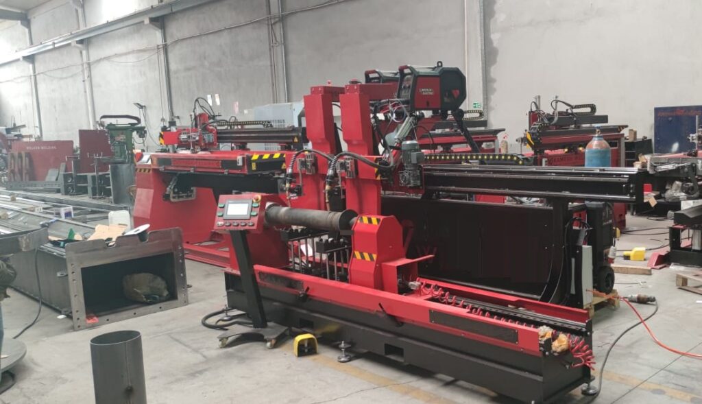
Automation in Laser Cutting and Welding Machines
Automation is playing an increasingly important role in laser cutting and welding machines. Automated laser cutting and welding machines offer a number of benefits, including:
Increased efficiency: Automated laser cutting and welding machines can significantly increase the efficiency of production by automating repetitive tasks, such as loading and unloading materials, positioning the laser head, and cutting or welding parts.
Improved quality: Automated laser cutting and welding machines can help to improve the quality of products by ensuring that parts are cut or welded consistently and accurately.
Reduced labor costs: Automated laser cutting and welding machines can help to reduce labor costs, especially for repetitive tasks.
Improved safety: Automated laser cutting and welding machines can help to improve the safety of workers by reducing the need for workers to perform dangerous tasks, such as working near high-power lasers and hot metal.
Here are some specific examples of how automation is being used in laser cutting and welding machines:
Automated loading and unloading: Automated laser cutting and welding machines can be equipped with automated loading and unloading systems. This allows the machines to operate unattended, which can further increase efficiency and reduce labor costs.
Automated positioning: Automated laser cutting and welding machines can be equipped with automated positioning systems. This allows the machines to precisely position the laser head, which ensures that parts are cut or welded accurately.
Automatic process control: Automated laser cutting and welding machines can be equipped with automatic process control systems. This allows the machines to monitor and control the cutting or welding process, which ensures that parts are cut or welded to the correct specifications.
Automated laser cutting and welding machines are used in a wide variety of industries, including:
Automotive industry: Automated laser cutting and welding machines are used in the automotive industry to cut and weld parts for cars, trucks, and other vehicles.
Electronics industry: Automated laser cutting and welding machines are used in the electronics industry to cut and weld circuit boards and other electronic components.
Food and beverage industry: Automated laser cutting and welding machines are used in the food and beverage industry to cut and weld packaging materials.
Medical device industry: Automated laser cutting and welding machines are used in the medical device industry to cut and weld medical devices, such as pacemakers and stents.
Consumer goods industry: Automated laser cutting and welding machines are used in the consumer goods industry to cut and weld a wide variety of consumer goods, such as toys, appliances, and household products.
The use of automation in laser cutting and welding machines is expected to grow in the coming years. As automation technology continues to develop, we can expect to see even more innovative and sophisticated automated laser cutting and welding solutions in the future.
Automated Loading and Unloading for Laser Cutting Machines
Automated loading and unloading is a key feature of many automated laser cutting and welding machines. Automated loading and unloading systems can help to increase the efficiency, productivity, and safety of laser cutting and welding operations.
There are a number of different types of automated loading and unloading systems available for laser cutting and welding machines. Some of the most common types include:
Robotic loading and unloading systems: Robotic loading and unloading systems use robots to load and unload materials from the laser cutting or welding machine. Robotic loading and unloading systems are very versatile and can be used to handle a wide variety of materials and shapes.
Conveyor belt loading and unloading systems: Conveyor belt loading and unloading systems use conveyor belts to transport materials to and from the laser cutting or welding machine. Conveyor belt loading and unloading systems are ideal for handling large volumes of materials.
Pallet loading and unloading systems: Pallet loading and unloading systems use pallets to load and unload materials from the laser cutting or welding machine. Pallet loading and unloading systems are ideal for handling heavy or bulky materials.
Automated loading and unloading systems offer a number of benefits, including:
Increased efficiency: Automated loading and unloading systems can help to significantly increase the efficiency of laser cutting and welding operations by eliminating the need for manual loading and unloading.
Improved productivity: Automated loading and unloading systems can help to improve the productivity of laser cutting and welding operations by allowing the machines to operate continuously.
Reduced labor costs: Automated loading and unloading systems can help to reduce labor costs, especially for repetitive tasks.
Improved safety: Automated loading and unloading systems can help to improve the safety of workers by reducing the need for workers to perform dangerous tasks, such as working near high-power lasers and hot metal.
Automated loading and unloading systems are becoming increasingly popular for laser cutting and welding machines. As the cost of automation technology continues to decrease, we can expect to see even more laser cutting and welding machines equipped with automated loading and unloading systems in the future.
Here are some specific examples of automated loading and unloading systems that are used with laser cutting and welding machines:
FANUC Arc Mate 100iD robot: The FANUC Arc Mate 100iD robot is a six-axis robot that can be used to load and unload materials from laser cutting and welding machines. The Arc Mate 100iD is a popular choice for automated loading and unloading because it is fast, accurate, and reliable.
ABB IRB 1600 robot: The ABB IRB 1600 robot is another six-axis robot that can be used to load and unload materials from laser cutting and welding machines. The IRB 1600 is similar to the Arc Mate 100iD in terms of its capabilities and performance.
KUKA KR 16 L robot: The KUKA KR 16 L robot is a lightweight robot that is ideal for automated loading and unloading of small and delicate parts. The KR 16 L is fast, accurate, and easy to program.
Automated loading and unloading systems are an essential part of many automated laser cutting and welding machines. Automated loading and unloading systems can help to improve the efficiency, productivity, safety, and cost-effectiveness of laser cutting and welding operations.
Automated Positioning
Automated positioning is a key feature of many automated laser cutting and welding machines. Automated positioning systems help to ensure that the laser head is precisely positioned relative to the workpiece, which results in high-quality cuts and welds.
There are a number of different types of automated positioning systems available for laser cutting and welding machines. Some of the most common types include:
Camera-based positioning systems: Camera-based positioning systems use cameras to identify and track the workpiece. The camera data is then used to control the movement of the laser head. Camera-based positioning systems are very accurate and can be used to position the laser head even in complex geometries.
Laser-based positioning systems: Laser-based positioning systems use lasers to measure the distance between the laser head and the workpiece. The laser data is then used to control the movement of the laser head. Laser-based positioning systems are very fast and can be used to position the laser head at very high speeds.
Encoder-based positioning systems: Encoder-based positioning systems use encoders to track the movement of the laser head. The encoder data is then used to control the movement of the laser head. Encoder-based positioning systems are very reliable and can be used to position the laser head with high accuracy.
Automated positioning systems offer a number of benefits, including:
Improved accuracy: Automated positioning systems help to ensure that the laser head is precisely positioned relative to the workpiece, which results in high-quality cuts and welds.
Increased speed: Automated positioning systems can help to increase the speed of laser cutting and welding operations by allowing the laser head to be positioned more quickly and accurately.
Reduced waste: Automated positioning systems can help to reduce waste by ensuring that the laser head is always positioned correctly.
Improved safety: Automated positioning systems can help to improve safety by reducing the need for workers to work near high-power lasers and hot metal.
Automated positioning systems are becoming increasingly common in laser cutting and welding machines. As the cost of automation technology continues to decrease, we can expect to see even more laser cutting and welding machines equipped with automated positioning systems in the future.
Here are some specific examples of automated positioning systems that are used with laser cutting and welding machines:
Precitec Proscan: The Precitec Proscan is a camera-based positioning system that is designed for laser cutting and welding machines. The Proscan is very accurate and can be used to position the laser head in complex geometries.
Scanlab IntelliSCAN: The Scanlab IntelliSCAN is another camera-based positioning system that is designed for laser cutting and welding machines. The IntelliSCAN is similar to the Proscan in terms of its capabilities and performance.
Raycus SmartScan: The Raycus SmartScan is a laser-based positioning system that is designed for laser cutting and welding machines. The SmartScan is very fast and can be used to position the laser head at very high speeds.
Automated positioning systems are an essential part of many automated laser cutting and welding machines. Automated positioning systems can help to improve the accuracy, speed, waste reduction, and safety of laser cutting and welding operations.
Automatic Process Control
Automatic process control is a system that uses sensors and software to monitor and control the laser cutting and welding process. Automatic process control systems can help to improve the quality, consistency, and efficiency of laser cutting and welding operations.
Automatic process control systems typically work by monitoring the following parameters:
Laser power: The laser power is the amount of energy that is being delivered to the workpiece. Automatic process control systems can adjust the laser power to ensure that the cut or weld is being made at the correct speed and temperature.
Laser speed: The laser speed is the speed at which the laser head is moving across the workpiece. Automatic process control systems can adjust the laser speed to ensure that the cut or weld is being made at the correct depth.
Focus: The focus of the laser beam is the point at which the laser beam is most concentrated. Automatic process control systems can adjust the focus of the laser beam to ensure that the cut or weld is being made at the correct location.
Gas flow: The gas flow is the amount of gas that is being used to protect the workpiece from oxidation. Automatic process control systems can adjust the gas flow to ensure that the cut or weld is being made in a clean environment.
Automatic process control systems can also use sensors to monitor the quality of the cut or weld. For example, a sensor can be used to measure the thickness of the cut or the strength of the weld. If the sensor detects that the cut or weld is not meeting the desired specifications, the automatic process control system can automatically adjust the laser power, speed, focus, or gas flow to correct the problem.
Automatic process control systems offer a number of benefits, including:
Improved quality: Automatic process control systems can help to improve the quality of laser cuts and welds by ensuring that the process is being controlled consistently.
Increased consistency: Automatic process control systems can help to increase the consistency of laser cuts and welds by compensating for variations in the workpiece material and environmental conditions.
Increased efficiency: Automatic process control systems can help to increase the efficiency of laser cutting and welding operations by reducing the need for manual intervention.
Reduced waste: Automatic process control systems can help to reduce waste by ensuring that the laser cuts and welds are being made as efficiently as possible.
Automatic process control systems are becoming increasingly common in laser cutting and welding machines. As the cost of automation technology continues to decrease, we can expect to see even more laser cutting and welding machines equipped with automatic process control systems in the future.
Here are some specific examples of automatic process control systems that are used with laser cutting and welding machines:
LPKF TruFlow: The LPKF TruFlow is an automatic process control system that is designed for laser cutting machines. The TruFlow uses sensors to monitor the laser power, speed, focus, and gas flow, and it automatically adjusts these parameters to ensure that the cut is made at the correct speed and temperature.
TRUMPF TruLaser Line 7000: The TRUMPF TruLaser Line 7000 is a laser cutting machine that is equipped with an automatic process control system. The TruLaser Line 7000 uses sensors to monitor the laser power, speed, focus, and gas flow, and it automatically adjusts these parameters to ensure that the cut is made at the correct speed and temperature.
MECCO Laser Pro2000: The MECCO Laser Pro2000 is a laser welding machine that is equipped with an automatic process control system. The MECCO Laser Pro2000 uses sensors to monitor the laser power, speed, focus, and gas flow, and it automatically adjusts these parameters to ensure that the weld is made at the correct speed and temperature.
Automatic process control systems are an essential part of many automated laser cutting and welding machines. Automatic process control systems can help to improve the quality, consistency, efficiency, and waste reduction of laser cutting and welding operations.
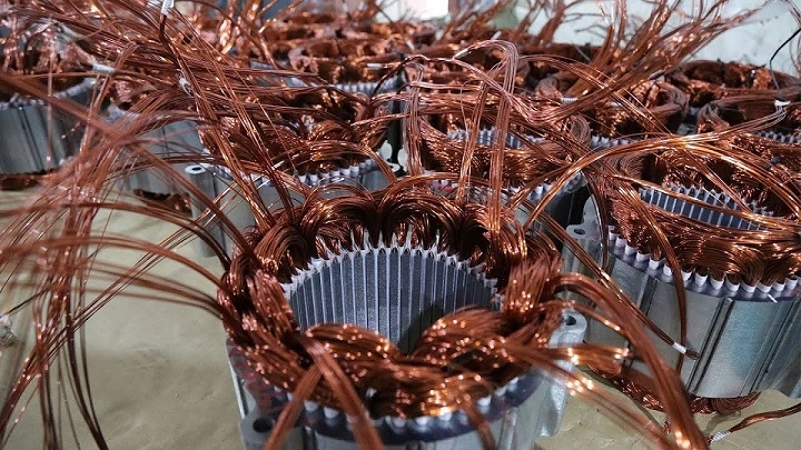
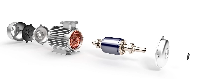
Winding machines for electric motor coils are used to wind the coils of electric motors. The coils are typically made of copper wire, which is wound around a bobbin or former. The bobbin or former is typically made of a material such as plastic, ceramic, or metal.
There are a variety of different types of winding machines for electric motor coils. Some of the most common types include:
Hand-operated winding machines: Hand-operated winding machines are the simplest type of winding machine. They are typically used for small-scale production or for winding coils with complex designs.
Semi-automatic winding machines: Semi-automatic winding machines use a combination of manual and automated steps. For example, the operator may load the wire onto the machine and then start the winding process. The machine will then automatically wind the coil and stop when it is finished.
Automatic winding machines: Automatic winding machines are the most sophisticated type of winding machine. They can be programmed to wind coils of different sizes, shapes, and designs. Automatic winding machines are typically used for large-scale production.
Winding machines for electric motor coils are used in a variety of industries, including automotive, electronics, and industrial machinery. They are essential for the production of electric motors.
Here are some of the benefits of using winding machines for electric motor coils:
Increased productivity: Winding machines for electric motor coils can help to increase productivity by reducing the time required to wind coils. This is because the machines can wind multiple coils simultaneously and can also be used to wind coils in parallel.
Improved quality: Winding machines for electric motor coils can help to improve the quality of wound coils by reducing the risk of errors. This is because the machines can be programmed to wind coils consistently and accurately.
Reduced costs: Winding machines for electric motor coils can help to reduce the costs associated with winding by eliminating the need for manual labor. This can free up workers to perform other tasks or to focus on quality control.
Increased safety: Winding machines for electric motor coils can help to improve safety by reducing the risk of accidents and injuries. This is because the machines can be programmed to perform tasks that would otherwise be hazardous for humans to perform.
Overall, winding machines for electric motor coils are a valuable asset for businesses that need to wind coils quickly, accurately, and cost-effectively.
CNC machining automation is the use of automated systems to control and operate CNC machines. This can include using programmable logic controllers (PLCs), robots, and other automated equipment to perform tasks such as loading and unloading workpieces, performing machining operations, and inspecting products.
CNC machining automation can offer a number of benefits, including:
Increased productivity: CNC machining automation can help to increase productivity by reducing the time required to machine parts. This is because the machines can perform multiple tasks simultaneously and can also be used to machine parts in parallel.
Improved quality: CNC machining automation can help to improve the quality of machined parts by reducing the risk of errors. This is because the machines can be programmed to perform tasks consistently and accurately.
Reduced costs: CNC machining automation can help to reduce the costs associated with machining by eliminating the need for manual labor. This can free up workers to perform other tasks or to focus on quality control.
Increased safety: CNC machining automation can help to improve safety by reducing the risk of accidents and injuries. This is because the machines can be programmed to perform tasks that would otherwise be hazardous for humans to perform.
CNC machining automation can be used to automate a wide variety of machining processes, including:
Milling
Turning
Drilling
Boring
Grinding
Wire EDM
Sinker EDM
There are a number of different ways to automate CNC machines. One common approach is to use a PLC to control the machine and any associated equipment. The PLC can be programmed to perform a variety of tasks, such as:
Controlling the movement of the machine axes
Activating and deactivating actuators and other devices
Controlling the flow of materials
Monitoring the process for errors
Another approach to automating CNC machines is to use robots. Robots can be used to perform tasks such as loading and unloading workpieces, performing machining operations, and inspecting products. Robots can also be used to index workpieces on a rotary table or to transfer workpieces between different machines.
The best approach to automating a CNC machine will depend on the specific needs of the business and the application. It is important to carefully consider the requirements of the process and the budget available before implementing an automation solution.
Here are some examples of CNC machining automation:
A fully automated CNC machining line that produces automotive engine blocks. The line uses robots to load and unload workpieces, perform machining operations, and inspect the finished products.
A CNC machining cell that uses a rotary table to index workpieces for machining on multiple sides. The cell is controlled by a PLC that coordinates the movement of the machine axes and the rotary table.
A CNC machining center that uses a robot to load and unload workpieces from a pallet. The robot also changes the tools in the machine spindle.
CNC machining automation can be a valuable asset for businesses that need to produce machined parts quickly, accurately, and cost-effectively.
Computer Numerical Control (CNC) is a manufacturing process that utilizes computerized systems to control machine tools and equipment. These systems interpret computer-aided design (CAD) files and convert them into precise movements of cutting tools or other machinery. Here’s a detailed explanation of CNC:
Precision Machining: CNC machining enables high precision and accuracy in manufacturing processes. It allows for intricate designs and complex shapes to be produced with consistency and reliability.
Automation: CNC systems automate the manufacturing process, reducing the need for manual intervention. This leads to increased efficiency, reduced labor costs, and higher production rates.
Versatility: CNC technology is versatile and can be applied to various manufacturing industries, including automotive, aerospace, electronics, medical, and consumer goods.
Flexibility: CNC machines can quickly switch between different tasks and production runs, making them suitable for small-batch and high-volume production alike.
CAD/CAM Integration: CNC machines are often integrated with computer-aided design (CAD) and computer-aided manufacturing (CAM) software, allowing designers and engineers to create and optimize parts digitally before machining.
Tooling: CNC machines utilize a wide range of cutting tools, including drills, end mills, lathes, routers, and grinders, to perform different machining operations such as milling, turning, drilling, and grinding.
Materials: CNC machining can work with a variety of materials, including metals (such as aluminum, steel, and titanium), plastics, wood, composites, and ceramics.
Accuracy and Repeatability: CNC systems offer high levels of accuracy and repeatability, ensuring consistent quality in manufactured parts.
Complex Geometry: CNC machining can produce parts with complex geometries that would be difficult or impossible to achieve using conventional machining methods.
Quality Control: CNC machines often include built-in quality control features such as measurement probes and feedback systems to ensure that parts meet specified tolerances and standards.
Cost-Effectiveness: While CNC machines may have higher upfront costs compared to manual machines, they offer long-term cost savings through increased productivity, reduced scrap, and improved efficiency.
Customization: CNC machining allows for easy customization of parts, making it ideal for prototyping and one-off production runs.
Overall, CNC technology revolutionizes the manufacturing industry by offering precision, efficiency, and flexibility in the production of a wide range of parts and components.
CNC Machining
CNC machining, short for Computer Numerical Control machining, is a manufacturing process that utilizes computerized controls and machine tools to remove material from a workpiece to create a custom-designed part or product. It’s widely used across various industries due to its precision, efficiency, and versatility. Here’s a detailed look at CNC machining:
CAD/CAM Design: The process begins with Computer-Aided Design (CAD) software, where engineers create a 3D model of the desired part. Then, Computer-Aided Manufacturing (CAM) software is used to generate toolpaths and instructions for the CNC machine based on the CAD model.
CNC Machine Setup: Once the program is created, it’s transferred to the CNC machine. The workpiece, typically a block of material such as metal, plastic, or wood, is securely mounted onto the machine bed or worktable. The cutting tools needed for the job are loaded into the machine’s tool turret or spindle.
Toolpath Execution: The CNC machine executes the programmed toolpaths, which dictate the precise movements of the cutting tools in relation to the workpiece. These movements include cutting, drilling, milling, turning, and other machining operations.
Material Removal: As the cutting tool moves across the workpiece according to the programmed instructions, it removes material to shape the part. The CNC machine’s high-speed spindle rotates the cutting tool at high RPMs, enabling efficient material removal.
Precision and Accuracy: CNC machining offers exceptional precision and accuracy, as the movements of the cutting tools are controlled by computer algorithms. This ensures that the finished parts meet tight tolerances and specifications consistently.
Versatility: CNC machines come in various configurations, including CNC mills, lathes, routers, grinders, and EDM (Electrical Discharge Machining) machines. Each type of CNC machine is suited for specific machining tasks and materials, providing versatility in manufacturing operations.
Complex Geometries: CNC machining can produce parts with intricate and complex geometries that would be challenging or impossible to manufacture using conventional machining methods. This capability makes it ideal for producing prototypes, custom components, and low-volume production runs.
Efficiency and Productivity: CNC machining offers high levels of efficiency and productivity, as it can run continuously with minimal operator intervention. This results in shorter lead times, reduced labor costs, and increased throughput compared to manual machining.
Quality Control: CNC machining often incorporates built-in quality control features, such as in-process measurement probes and inspection routines, to ensure that the finished parts meet specified quality standards and tolerances.
Post-Processing: After machining, the finished parts may undergo additional post-processing operations such as deburring, surface finishing, heat treatment, or assembly to achieve the desired final product.
CNC machining plays a crucial role in modern manufacturing, enabling the production of precision parts and components for a wide range of industries, including aerospace, automotive, electronics, medical, and consumer goods. Its combination of accuracy, efficiency, and versatility makes it a cornerstone of advanced manufacturing processes.
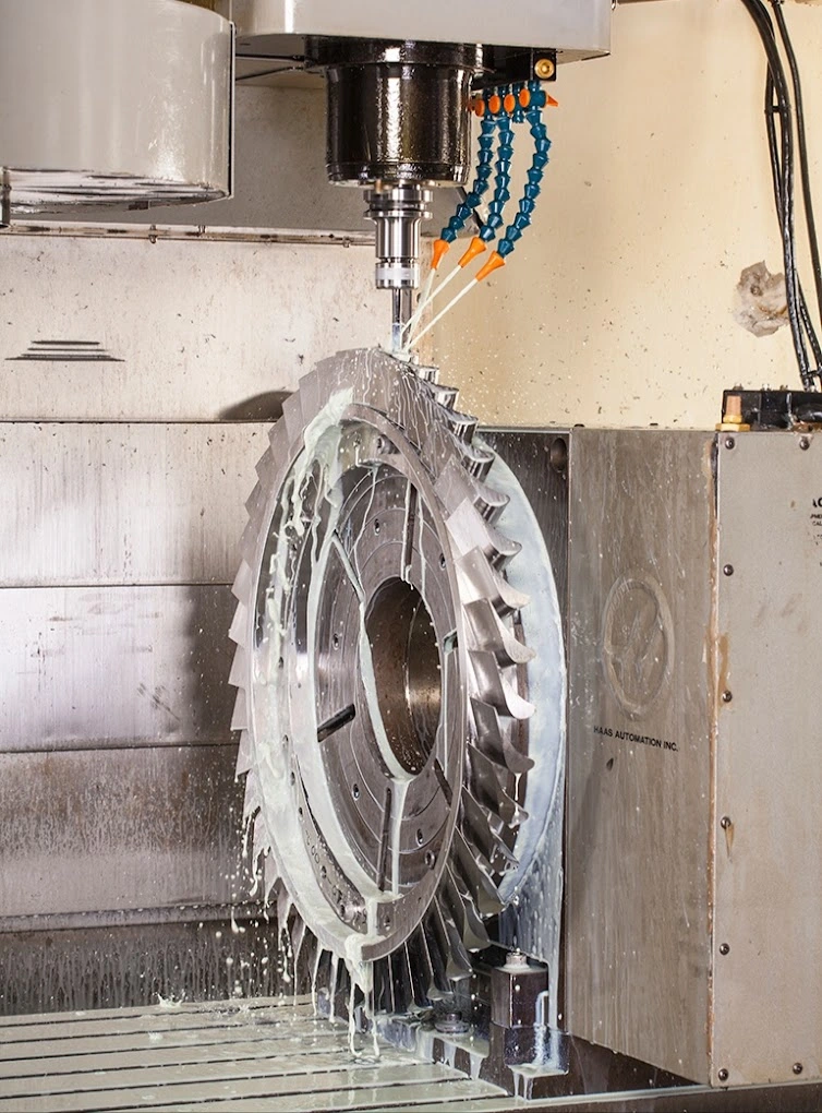
CNC Milling
CNC milling is a machining process that uses computerized controls and rotating cutting tools to remove material from a workpiece to create custom-designed parts or components with precise dimensions and shapes. It’s a highly versatile and widely used manufacturing method across various industries. Here’s an in-depth overview of CNC milling:
Machine Setup: The CNC milling process begins with the setup of the workpiece and the milling machine. The workpiece, typically a block of material such as metal or plastic, is securely clamped to the milling machine’s worktable or fixture. The CNC machine operator then loads the appropriate cutting tools into the machine’s tool magazine or spindle.
Toolpath Generation: Once the workpiece is secured, the CNC operator inputs the machining instructions into the machine’s computerized control system. These instructions include the specific toolpaths that the cutting tools will follow to remove material from the workpiece. Toolpaths are generated using Computer-Aided Design (CAD) and Computer-Aided Manufacturing (CAM) software, which translate the design specifications into machine-readable code (G-code).
Tool Selection: CNC milling machines are equipped with a variety of cutting tools, including end mills, face mills, ball mills, and drills, each designed for specific machining tasks and materials. The CNC operator selects the appropriate cutting tools based on the part geometry, material properties, and machining requirements.
Material Removal: With the workpiece secured and the cutting tools loaded, the CNC milling machine begins the machining process. The machine’s spindle rotates the cutting tool at high speeds, while the CNC control system precisely guides the tool along the programmed toolpaths. As the cutting tool engages with the workpiece, it removes material layer by layer, shaping the part according to the CAD design.
Precision and Accuracy: CNC milling offers exceptional precision and accuracy, allowing for tight tolerances and complex geometries to be achieved consistently. The computerized control system ensures that each machining operation is performed with exacting precision, resulting in high-quality finished parts.
Versatility: CNC milling machines are capable of performing a wide range of machining operations, including face milling, peripheral milling, slot milling, drilling, tapping, and contouring. This versatility allows for the production of parts with intricate features and complex shapes.
Efficiency and Productivity: CNC milling offers high levels of efficiency and productivity compared to manual milling processes. Once the machining program is set up, the CNC machine can run continuously with minimal operator intervention, resulting in shorter lead times and increased throughput.
Quality Control: CNC milling machines often incorporate built-in quality control features, such as in-process measurement probes and tool wear monitoring systems, to ensure that the finished parts meet specified quality standards and tolerances.
Post-Processing: After machining, the finished parts may undergo additional post-processing operations such as deburring, surface finishing, or heat treatment to achieve the desired final product.
CNC milling plays a critical role in modern manufacturing, enabling the production of precision parts and components for a wide range of industries, including aerospace, automotive, medical, electronics, and consumer goods. Its combination of accuracy, versatility, and efficiency makes it an essential technology in advanced manufacturing processes.
CNC Turning
CNC turning is a machining process that utilizes computer numerical control (CNC) technology to produce cylindrical parts by removing material from a rotating workpiece. This process is commonly used to create parts such as shafts, bolts, and bushings. Here’s a detailed explanation of CNC turning:
Machine Setup: The CNC turning process begins with the setup of the workpiece and the CNC lathe machine. The workpiece, typically a cylindrical or rod-shaped material such as metal or plastic, is securely clamped into the lathe’s chuck or collet. The CNC operator then loads the required cutting tools into the lathe’s tool turret or toolpost.
Toolpath Generation: Once the workpiece is secured, the CNC operator inputs the machining instructions into the lathe’s computerized control system. These instructions include the specific toolpaths that the cutting tools will follow to remove material from the workpiece. Toolpaths are generated using Computer-Aided Design (CAD) and Computer-Aided Manufacturing (CAM) software, which translate the design specifications into machine-readable code (G-code).
Tool Selection: CNC turning machines are equipped with a variety of cutting tools, including turning tools, boring tools, threading tools, and grooving tools. The CNC operator selects the appropriate cutting tools based on the part geometry, material properties, and machining requirements.
Material Removal: With the workpiece secured and the cutting tools loaded, the CNC turning machine begins the machining process. The workpiece rotates at high speed, while the cutting tool moves along the programmed toolpaths to remove material from the outer diameter (OD) and/or inner diameter (ID) of the workpiece. This process creates the desired cylindrical shape and features on the part.
Precision and Accuracy: CNC turning offers high precision and accuracy, allowing for tight tolerances and smooth surface finishes to be achieved consistently. The computerized control system ensures that each machining operation is performed with exacting precision, resulting in high-quality finished parts.
Versatility: CNC turning machines are capable of producing a wide range of cylindrical parts with varying diameters, lengths, and features. They can perform operations such as facing, turning, grooving, threading, and drilling, making them suitable for a variety of applications across different industries.
Efficiency and Productivity: CNC turning offers high levels of efficiency and productivity compared to manual turning processes. Once the machining program is set up, the CNC machine can run continuously with minimal operator intervention, resulting in shorter lead times and increased throughput.
Quality Control: CNC turning machines often incorporate built-in quality control features, such as in-process measurement probes and tool wear monitoring systems, to ensure that the finished parts meet specified quality standards and tolerances.
Post-Processing: After machining, the finished parts may undergo additional post-processing operations such as deburring, surface finishing, or heat treatment to achieve the desired final product.
CNC turning is widely used in various industries, including automotive, aerospace, medical, and electronics, for the production of precision cylindrical parts. Its combination of accuracy, versatility, and efficiency makes it an essential technology in modern manufacturing processes.
CNC Programming
CNC programming is the process of creating a set of instructions that control the operation of a computer numerical control (CNC) machine. These instructions, often referred to as G-code or CNC code, tell the CNC machine how to move its cutting tools to shape and form a workpiece according to a specified design. Here’s an overview of CNC programming:
CAD/CAM Software: CNC programming typically begins with the creation of a digital design using Computer-Aided Design (CAD) software. The CAD model defines the geometry and dimensions of the part to be machined. Once the design is complete, Computer-Aided Manufacturing (CAM) software is used to generate the toolpaths and G-code necessary for machining the part.
Toolpath Generation: In CAM software, the CNC programmer selects the cutting tools to be used and specifies the machining operations required to produce the part. The CAM software generates toolpaths, which are the paths that the cutting tools will follow to remove material from the workpiece. Toolpaths are generated based on factors such as tool geometry, cutting parameters, and part geometry.
G-Code Generation: Once the toolpaths are generated, the CAM software converts them into machine-readable G-code. G-code is a standardized programming language that CNC machines understand. It consists of a series of commands and coordinates that instruct the CNC machine on how to move its axes and operate its cutting tools to machine the part.
Programming Considerations: CNC programmers must consider various factors when writing CNC programs, including tool selection, cutting speeds and feeds, toolpath optimization, tool changes, workpiece fixturing, and safety considerations. They must also take into account the capabilities and limitations of the CNC machine and the materials being machined.
Simulation and Verification: Before running a CNC program on an actual machine, programmers often simulate the machining process using CAM software or dedicated simulation tools. This allows them to visualize the toolpaths, detect potential collisions or errors, and verify that the program will produce the desired results.
Editing and Optimization: CNC programs may need to be edited or optimized to improve efficiency, accuracy, or tool life. Programmers can adjust parameters such as cutting speeds, toolpaths, or machining strategies to achieve better results. They may also use post-processing software to customize the G-code output for specific CNC machines.
Documentation: Proper documentation of CNC programs is essential for traceability and repeatability in manufacturing operations. CNC programmers often create detailed setup sheets, tool lists, and program notes to accompany CNC programs and provide instructions for machine setup and operation.
Training and Skills: CNC programming requires a solid understanding of machining principles, CNC machine operation, CAD/CAM software, and G-code programming. Many CNC programmers undergo specialized training or certification programs to develop their skills and expertise in CNC programming.
Overall, CNC programming is a critical aspect of modern manufacturing, enabling the efficient and precise machining of complex parts across a wide range of industries. With the advancement of CAD/CAM technology and CNC machine capabilities, CNC programming continues to evolve to meet the demands of increasingly complex and sophisticated manufacturing processes.
CNC Router
A CNC router is a computer-controlled cutting machine used for cutting various materials, including wood, plastics, metals, and composites. It operates similarly to a handheld router but is controlled by a computerized system that precisely guides the cutting tool along programmed paths to create intricate designs, shapes, and patterns. Here’s an overview of CNC routers:
Machine Structure: CNC routers consist of a rigid frame or gantry structure that supports a worktable and a movable cutting head or spindle assembly. The cutting head typically holds a rotating cutting tool, such as a router bit or end mill, which removes material from the workpiece as it moves across the surface.
Computer Control: CNC routers are controlled by computer numerical control (CNC) systems, which interpret digital design files and convert them into machine-readable instructions. These instructions, often referred to as G-code, dictate the precise movements of the cutting tool, including speed, direction, and depth of cut.
CAD/CAM Software: The CNC programming process begins with the creation of a digital design using Computer-Aided Design (CAD) software. The design file is then imported into Computer-Aided Manufacturing (CAM) software, where toolpaths are generated based on the desired geometry and machining operations.
Toolpath Generation: In CAM software, CNC programmers specify the cutting tools to be used and define the toolpaths that the cutting head will follow to machine the part. Toolpaths can include operations such as cutting, drilling, engraving, and carving, depending on the requirements of the design.
Material Fixturing: The workpiece is secured to the CNC router’s worktable using clamps, vacuum hold-downs, or other fixturing methods to ensure stability during machining. Proper fixturing is essential to prevent movement or vibration of the workpiece, which can affect machining accuracy and quality.
Material Removal: Once the workpiece is secured, the CNC router executes the programmed toolpaths, moving the cutting head across the surface of the material to remove material and create the desired features. The cutting tool may vary depending on the material being machined and the specific machining operation.
Precision and Accuracy: CNC routers offer high precision and accuracy, allowing for intricate designs and tight tolerances to be achieved consistently. The computerized control system ensures that each machining operation is performed with exacting precision, resulting in high-quality finished parts.
Versatility: CNC routers are versatile machines capable of machining a wide range of materials, including wood, plastics, metals, foam, and composites. They are commonly used in industries such as woodworking, sign making, prototyping, furniture manufacturing, and aerospace.
Applications: CNC routers are used for a variety of applications, including cutting, carving, routing, engraving, drilling, and milling. They are employed in industries ranging from woodworking and cabinetry to automotive and aerospace for the production of custom parts, prototypes, molds, and decorative elements.
Safety Considerations: Proper safety precautions must be observed when operating CNC routers, including wearing personal protective equipment (PPE), securing workpieces effectively, and following machine-specific safety guidelines. Training and awareness of potential hazards are essential for safe operation.
Overall, CNC routers are versatile and powerful machines that offer precision, efficiency, and flexibility in the machining of a wide range of materials and applications. They play a crucial role in modern manufacturing and fabrication processes, enabling the production of complex and customized parts with high accuracy and repeatability.
CNC Lathe
A CNC lathe, also known as a computer numerical control lathe, is a machine tool used for machining cylindrical workpieces. It operates by rotating the workpiece while a cutting tool is fed into it to remove material and create desired shapes, features, and surfaces. Here’s a comprehensive overview of CNC lathes:
Machine Structure: A CNC lathe consists of a horizontal or vertical bed, a spindle, a chuck or collet for holding the workpiece, and a tool turret or toolpost that holds various cutting tools. The machine may also feature additional components such as a tailstock for supporting longer workpieces and a coolant system for chip removal and temperature control.
Computer Control: CNC lathes are controlled by a computerized system that interprets digital design files and generates machine-readable instructions, typically in the form of G-code. The CNC system precisely controls the movements of the cutting tools and the rotation of the workpiece to execute programmed machining operations.
CAD/CAM Software: The CNC programming process begins with the creation of a digital design using Computer-Aided Design (CAD) software. The design file is then imported into Computer-Aided Manufacturing (CAM) software, where toolpaths are generated based on the desired geometry and machining operations.
Toolpath Generation: In CAM software, CNC programmers specify the cutting tools to be used and define the toolpaths that the cutting tools will follow to machine the part. Toolpaths can include operations such as turning, facing, grooving, threading, and drilling, depending on the requirements of the design.
Workpiece Fixturing: The workpiece is mounted on the lathe’s chuck or collet and secured in place to ensure stability during machining. Proper fixturing is critical to prevent movement or vibration of the workpiece, which can affect machining accuracy and quality.
Material Removal: Once the workpiece is secured, the CNC lathe executes the programmed toolpaths, moving the cutting tools along the surface of the rotating workpiece to remove material and create the desired features. The cutting tools may be indexed automatically by the tool turret or manually changed as needed.
Precision and Accuracy: CNC lathes offer high precision and accuracy, allowing for tight tolerances and smooth surface finishes to be achieved consistently. The computerized control system ensures that each machining operation is performed with exacting precision, resulting in high-quality finished parts.
Versatility: CNC lathes are versatile machines capable of machining a wide range of materials, including metals, plastics, and composites. They are commonly used in industries such as aerospace, automotive, medical, and electronics for the production of shafts, bushings, fittings, and other cylindrical components.
Applications: CNC lathes are used for various turning operations, including external turning, internal turning, facing, threading, grooving, and taper turning. They are employed in both production and prototyping applications to create customized parts with precise dimensions and surface finishes.
Safety Considerations: Proper safety precautions must be observed when operating CNC lathes, including wearing personal protective equipment (PPE), securing workpieces effectively, and following machine-specific safety guidelines. Training and awareness of potential hazards are essential for safe operation.
Overall, CNC lathes are essential machines in modern manufacturing and fabrication processes, offering precision, efficiency, and flexibility in the machining of cylindrical workpieces. They play a crucial role in producing a wide range of components for various industries, contributing to advancements in technology and innovation.
CNC Controller
A CNC controller is the central component of a computer numerical control (CNC) system, responsible for interpreting digital instructions and controlling the operation of a CNC machine. It receives input from the operator or CAD/CAM software and translates this information into machine-readable commands to drive the motion of the machine’s axes and activate its cutting tools. Here’s an in-depth look at CNC controllers:
Hardware Components: A CNC controller typically consists of several hardware components, including a central processing unit (CPU), memory, input/output (I/O) interfaces, servo or stepper motor drivers, and a user interface. These components work together to execute programmed machining operations accurately and efficiently.
Control Software: The CNC controller runs specialized control software that interprets digital design files (such as CAD drawings or CAM toolpaths) and converts them into machine-readable instructions, often in the form of G-code. The control software may also include features for toolpath optimization, tool change management, and error detection.
Interpolation: One of the key functions of a CNC controller is interpolation, which involves calculating the precise motion of the machine’s axes to follow programmed toolpaths smoothly and accurately. Interpolation algorithms determine how the machine moves between consecutive points in the toolpath, taking into account factors such as feed rate, acceleration, and jerk (rate of change of acceleration).
Axis Control: The CNC controller controls the movement of the machine’s axes, which may include linear axes (X, Y, Z) for positioning in three-dimensional space and rotary axes (A, B, C) for rotational motion. It sends commands to servo or stepper motor drivers to move the axes to specific positions with high precision and repeatability.
Speed and Feed Control: The CNC controller regulates the speed and feed rates of the machine’s cutting tools during machining operations. It adjusts spindle speed, cutting feed rate, and rapid traverse rate based on programmed parameters and material properties to optimize machining efficiency and surface finish.
Tool Management: Some CNC controllers support automatic tool changers, which allow the machine to switch between different cutting tools during machining without manual intervention. The controller manages tool selection, tool positioning, and tool changeover sequences to minimize downtime and maximize productivity.
Safety Features: CNC controllers often include safety features to protect operators and equipment during machining operations. These may include emergency stop buttons, collision detection systems, overtravel limits, and interlocks to prevent unauthorized access to the machine.
Monitoring and Diagnostics: Many CNC controllers offer monitoring and diagnostics features to track machine performance, detect errors or abnormalities, and troubleshoot issues. They may provide real-time feedback on spindle load, motor temperature, tool wear, and other relevant parameters to ensure optimal operation.
User Interface: The user interface of a CNC controller allows operators to interact with the machine, input machining parameters, load and execute CNC programs, and monitor the progress of machining operations. It may consist of a touchscreen display, keypad, jog wheel, or other input devices.
Networking and Connectivity: Some CNC controllers support networking and connectivity features, allowing them to communicate with external devices such as computers, servers, and manufacturing execution systems (MES). This enables remote monitoring, data transfer, and integration with other systems for seamless workflow management.
CNC controllers play a crucial role in modern manufacturing, enabling precise and efficient machining of complex parts across a wide range of industries. Their advanced capabilities and features contribute to the automation, productivity, and quality of CNC machining processes.
CNC Machine Tools
CNC machine tools are computer-controlled devices used for machining various materials to create precise and complex parts. These machines are equipped with cutting tools that are guided by computer numerical control (CNC) systems to perform machining operations such as cutting, drilling, milling, turning, and grinding. Here’s an in-depth overview of CNC machine tools:
Types of CNC Machine Tools:
CNC Milling Machines: These machines use rotating cutting tools to remove material from a workpiece to create flat or contoured surfaces. They are commonly used for producing prismatic parts with complex geometries.
CNC Turning Centers: Also known as CNC lathes, these machines rotate the workpiece while a stationary cutting tool removes material to create cylindrical shapes or features.
CNC Drilling Machines: These machines use rotating drill bits to create holes in workpieces. They are used for drilling, counterboring, countersinking, and tapping operations.
CNC Grinding Machines: These machines use abrasive wheels to remove material from a workpiece to achieve high surface quality and dimensional accuracy. They are used for precision grinding of surfaces, profiles, and cylindrical parts.
CNC Laser Cutting Machines: These machines use laser beams to cut through materials such as metal, plastic, and wood. They are commonly used for cutting sheet metal and other flat materials.
CNC Plasma Cutting Machines: Similar to laser cutting machines, these machines use a plasma torch to cut through electrically conductive materials such as steel, aluminum, and copper.
CNC Waterjet Cutting Machines: These machines use a high-pressure jet of water mixed with abrasive particles to cut through a wide range of materials, including metal, stone, glass, and composites.
Components of CNC Machine Tools:
Machine Bed: The base structure of the machine that supports the workpiece and cutting tools.
Spindle: The rotating shaft that holds the cutting tool in milling machines and drilling machines.
Chuck or Collet: The device used to hold and secure the workpiece in turning centers and milling machines.
Tool Turret or Toolpost: The mechanism that holds multiple cutting tools and allows for tool changes in turning centers and milling machines.
Axis Drives: The motors and actuators that move the machine’s axes (X, Y, Z, and optionally A, B, C) to position the cutting tool relative to the workpiece.
CNC Control System: The computerized system that interprets digital design files, generates machine instructions (G-code), and controls the movement of the machine’s axes and cutting tools.
Coolant System: The system that delivers coolant or lubricant to the cutting area to remove heat and chips, improve surface finish, and prolong tool life.
Operation of CNC Machine Tools:
Programming: CNC machine tools are programmed using Computer-Aided Design (CAD) and Computer-Aided Manufacturing (CAM) software. The programmer creates a digital design of the part and generates toolpaths that specify the motion of the cutting tool.
Setup: The workpiece is loaded onto the machine and secured in place using clamps, fixtures, or chucks. The cutting tools are installed and aligned according to the programmed toolpaths.
Machining: The CNC control system executes the programmed toolpaths, guiding the cutting tools to remove material from the workpiece as per the design specifications.
Monitoring and Quality Control: Operators monitor the machining process, checking for issues such as tool wear, surface finish, and dimensional accuracy. Quality control measures, such as inspection and measurement, may be performed to ensure that the finished parts meet specifications.
Maintenance: Regular maintenance tasks, such as cleaning, lubrication, and tool replacement, are performed to keep the machine in optimal condition and prevent downtime.
Advantages of CNC Machine Tools:
Precision: CNC machine tools offer high precision and accuracy, resulting in consistent and repeatable part quality.
Versatility: They can perform a wide range of machining operations on various materials, making them suitable for diverse applications.
Efficiency: CNC machine tools can run continuously with minimal operator intervention, leading to increased productivity and reduced lead times.
Complexity: They can produce complex parts with intricate geometries that would be difficult or impossible to machine manually.
Automation: CNC machine tools enable automation of repetitive tasks, freeing up operators for more skilled and value-added activities.
Applications of CNC Machine Tools:
CNC machine tools are used in industries such as aerospace, automotive, medical, electronics, and manufacturing for producing parts and components used in various products and systems.
Common applications include prototyping, production machining, mold making, tool and die manufacturing, and customization of parts for specific applications.
In summary, CNC machine tools are versatile and essential equipment in modern manufacturing, offering precision, efficiency, and flexibility in the production of complex parts across a wide range of industries and applications.
CNC Software
CNC software refers to the specialized computer programs used to create, edit, simulate, and control computer numerical control (CNC) machines. These software packages play a crucial role in the CNC machining process by enabling users to design parts, generate toolpaths, and convert designs into machine-readable code. Here’s an overview of CNC software:
CAD/CAM Software:
Computer-Aided Design (CAD) Software: CAD software is used to create digital models of parts and assemblies. It allows users to design 2D drawings or 3D models by specifying dimensions, shapes, and features. CAD models serve as the foundation for generating toolpaths in CAM software.
Computer-Aided Manufacturing (CAM) Software: CAM software translates CAD models into machine instructions (G-code) by generating toolpaths based on specified machining operations and parameters. It determines the optimal toolpath for cutting, milling, turning, and other machining processes, taking into account factors such as tool geometry, material properties, and machining strategies.
Simulation Software:
CNC Machine Simulation: Simulation software allows users to visualize and simulate the machining process before it is executed on a CNC machine. It provides a virtual representation of the machine tool, workpiece, and cutting tool, allowing users to verify toolpaths, detect potential collisions, and optimize machining operations.
Material Removal Simulation: Some simulation software packages offer advanced features for simulating material removal and chip formation during machining. This allows users to evaluate cutting forces, tool wear, and surface finish, providing valuable insights for process optimization and toolpath refinement.
Controller Software:
CNC Controller Software: CNC controller software runs on the CNC machine’s control unit and interprets machine instructions (G-code) to control the movement of the machine’s axes and activate its cutting tools. It provides features for program execution, toolpath visualization, error handling, and machine monitoring.
Post-Processing Software:
Post-Processor: Post-processing software converts CAM-generated toolpaths into machine-specific G-code that is compatible with a particular CNC machine. It translates general machining instructions into machine-specific commands, such as axis movements, spindle speed, and tool changes, ensuring compatibility and accuracy when running CNC programs on different machines.
Toolpath Editing Software:
Toolpath Editing: Toolpath editing software allows users to modify and optimize toolpaths generated by CAM software. It provides tools for adjusting cutting parameters, adding or removing toolpath segments, specifying machining sequences, and optimizing toolpath efficiency to improve machining performance and quality.
CAD/CAM Integration:
Integrated Solutions: Some CNC software packages offer integrated CAD/CAM functionality, allowing users to design parts and generate toolpaths within the same software environment. Integrated solutions streamline the workflow, eliminate data translation errors, and provide seamless integration between design and manufacturing processes.
Additive Manufacturing Software:
3D Printing Software: For additive manufacturing processes such as 3D printing, specialized software packages are used to prepare digital models for printing, slice them into printable layers, and generate machine-specific instructions for additive manufacturing machines. These software packages provide features for model optimization, support generation, and build platform setup.
Nesting Software:
Nesting Optimization: Nesting software is used for optimizing material utilization and arranging parts on raw material sheets efficiently. It automatically arranges parts in the most space-efficient manner, minimizing material waste and maximizing production yield. Nesting software is commonly used in sheet metal fabrication, woodworking, and other industries where material efficiency is critical.
Cloud-Based Solutions:
Cloud-Based CNC Software: Cloud-based CNC software solutions offer online collaboration, storage, and access to CNC programming and simulation tools from any internet-enabled device. These platforms provide flexibility, scalability, and accessibility, allowing users to work remotely, collaborate with team members, and manage CNC projects more effectively.
Vendor-Specific Software:
Manufacturer-Specific Software: Some CNC machine manufacturers offer proprietary software solutions tailored to their machines. These software packages may include custom features, machine-specific optimizations, and proprietary file formats designed to enhance performance, compatibility, and ease of use with their machines.
In summary, CNC software encompasses a range of specialized tools and applications designed to facilitate the design, programming, simulation, and control of CNC machines. These software packages play a critical role in modern manufacturing by enabling efficient and accurate production of complex parts across a wide range of industries and applications.
CNC Precision
CNC precision refers to the level of accuracy and repeatability achieved in the machining process using computer numerical control (CNC) machines. It is a crucial factor in manufacturing, as precision directly impacts the quality, functionality, and performance of machined parts. Here’s a detailed explanation of CNC precision:
Accuracy: Accuracy in CNC machining refers to how closely the actual dimensions of a machined part match the intended dimensions specified in the design. CNC machines are capable of achieving high levels of accuracy, often within tenths or even thousandths of an inch (or a few micrometers). Factors that influence accuracy include machine calibration, tool wear, cutting parameters, and material properties.
Repeatability: Repeatability refers to the ability of a CNC machine to consistently reproduce the same results over multiple machining operations. A CNC machine with high repeatability will produce identical parts when given the same input and operating conditions. Repeatability is essential for maintaining consistency and quality in mass production and repetitive machining tasks.
Tolerance: Tolerance is the allowable deviation from a specified dimension, indicating the acceptable variation in the dimensions of a machined part. Tighter tolerances require higher precision in machining. CNC machines are capable of holding tight tolerances, allowing for the production of parts with precise dimensions and fitment. Tolerance requirements vary depending on the application and the specific requirements of the part.
Machine Rigidity: CNC machine rigidity plays a significant role in achieving precision. A rigid machine structure minimizes vibrations and deflections during cutting, resulting in more accurate and consistent machining. High-quality CNC machines are constructed from rigid materials and feature robust components to maintain stability and accuracy during operation.
Tooling: The selection and condition of cutting tools also affect CNC precision. High-quality, sharp tools with proper geometries and coatings contribute to better surface finish, dimensional accuracy, and tool life. Tool wear and deflection can degrade precision over time, necessitating regular tool inspection, maintenance, and replacement.
Workholding: Proper workholding is essential for maintaining part stability and alignment during machining. Securely clamping the workpiece prevents movement or vibration, ensuring consistent machining accuracy. Various workholding devices, such as vises, fixtures, and chucks, are used to hold workpieces securely in place during CNC machining operations.
Machine Calibration and Maintenance: Regular calibration and maintenance of CNC machines are critical for ensuring precision and accuracy. Calibration procedures verify the accuracy of machine positioning, axis alignment, spindle concentricity, and tool offsets. Routine maintenance tasks, such as lubrication, cleaning, and inspection, help prevent wear and maintain machine performance over time.
Programming and Toolpath Optimization: Efficient CNC programming and toolpath optimization contribute to precision machining. Optimized toolpaths minimize tool deflection, reduce cutting forces, and improve chip evacuation, resulting in better surface finish and dimensional accuracy. Advanced CAM software allows for the generation of optimized toolpaths based on machining parameters, material properties, and part geometry.
Material Properties: Material selection and properties also impact CNC precision. Different materials have varying machinability characteristics, such as hardness, toughness, and thermal conductivity, which affect machining performance and tool life. Understanding material behavior and selecting appropriate cutting parameters are essential for achieving precise machining results.
Quality Control Measures: Implementing robust quality control measures is essential for verifying CNC precision and ensuring part conformance to specifications. Inspection techniques such as dimensional measurement, surface roughness analysis, and geometric verification are used to validate part accuracy and identify deviations from the desired tolerances.
In summary, CNC precision encompasses various factors that contribute to the accuracy, repeatability, and quality of machined parts. Achieving high precision requires careful consideration of machine rigidity, tooling, workholding, calibration, programming, material properties, and quality control measures. By optimizing these factors, CNC machining operations can consistently produce parts with tight tolerances and superior precision to meet the demands of modern manufacturing industries.
CNC Automation
CNC automation refers to the integration of computer numerical control (CNC) technology with automated systems and processes to improve productivity, efficiency, and flexibility in manufacturing operations. By leveraging automation, CNC machines can perform tasks with minimal human intervention, leading to increased throughput, reduced cycle times, and enhanced overall performance. Here’s an in-depth look at CNC automation:
Automated Tool Changes: CNC machines can be equipped with automatic tool changers (ATCs) that allow for the automatic swapping of cutting tools during machining operations. ATCs enable seamless tool changes without operator intervention, reducing downtime and increasing machining efficiency.
Material Handling Systems: Automated material handling systems, such as robotic arms, conveyor belts, and gantry loaders, can be integrated with CNC machines to automate the loading and unloading of workpieces. These systems streamline material flow, minimize manual labor, and enable continuous production runs.
Pallet Changers: Pallet changers are automation devices that enable the quick exchange of workpiece pallets on CNC machining centers. By pre-loading multiple pallets with workpieces, operators can reduce setup times and maximize machine utilization. Pallet changers facilitate unmanned machining operations and support high-mix, low-volume production.
Bar Feeders and Bar Loaders: In CNC turning applications, bar feeders and bar loaders automate the feeding of raw material (such as round stock or bar stock) into the machine. These devices eliminate the need for manual material handling, allowing for continuous machining of long production runs.
Robotics Integration: Industrial robots can be integrated with CNC machines to perform tasks such as part loading, unloading, inspection, and palletizing. Robotic automation enhances production flexibility, accelerates cycle times, and enables lights-out machining for unmanned operations.
CNC Cell and Flexible Manufacturing Systems: CNC cells and flexible manufacturing systems (FMS) combine multiple CNC machines with automated material handling and part transfer systems. These systems create highly flexible production environments capable of producing a wide range of parts with minimal setup and changeover times.
Lights-Out Machining: Lights-out machining refers to the practice of running CNC machines autonomously, without human supervision, typically during off-hours or overnight. By leveraging automation, lights-out machining enables continuous production operations, maximizes machine utilization, and reduces labor costs.
Automated Inspection Systems: Automated inspection systems, such as coordinate measuring machines (CMMs) and vision systems, can be integrated with CNC machines to perform in-process and post-process inspection of machined parts. These systems ensure product quality, detect defects, and provide feedback for process optimization.
In-Process Monitoring and Control: CNC machines equipped with sensors and monitoring systems can automatically monitor process parameters such as cutting forces, tool wear, temperature, and vibration. Real-time data analysis allows for adaptive control strategies to optimize machining performance and prevent tool breakage or workpiece damage.
Software Automation: Advanced CNC software solutions offer automation features for programming, toolpath optimization, simulation, and scheduling. Automated software tools streamline the programming workflow, generate efficient toolpaths, simulate machining operations, and optimize production schedules based on machine capacity and resource availability.
Remote Monitoring and Control: Remote monitoring and control systems enable operators to monitor CNC machines and production processes from remote locations via computer networks or mobile devices. Real-time data visualization, alerts, and notifications facilitate proactive decision-making, troubleshooting, and maintenance scheduling.
Integration with Manufacturing Execution Systems (MES): CNC automation can be integrated with MES software platforms to enable seamless data exchange and workflow orchestration across the manufacturing enterprise. MES systems provide centralized control and visibility into production operations, enabling optimization of resources, schedules, and quality management.
In summary, CNC automation encompasses a wide range of technologies and strategies aimed at enhancing the efficiency, flexibility, and productivity of CNC machining operations. By integrating automated systems, robotics, software solutions, and advanced control strategies, manufacturers can optimize production processes, reduce labor costs, and maintain a competitive edge in today’s dynamic manufacturing environment.
CNC Manufacturing
CNC manufacturing refers to the process of using computer numerical control (CNC) machines to produce parts and components with high precision and accuracy. CNC manufacturing encompasses a wide range of machining operations, including milling, turning, drilling, grinding, and additive manufacturing processes such as 3D printing. Here’s an overview of CNC manufacturing:
Design and Engineering: The CNC manufacturing process typically begins with the design and engineering phase. Engineers use computer-aided design (CAD) software to create digital models of the parts or components to be manufactured. CAD models define the geometry, dimensions, tolerances, and other specifications of the part.
CAM Programming: Once the design is finalized, computer-aided manufacturing (CAM) software is used to generate toolpaths and CNC programs based on the CAD model. CAM programming involves selecting the appropriate cutting tools, machining strategies, cutting parameters, and toolpaths to achieve the desired part geometry and surface finish.
Tooling Selection: CNC machining requires the selection of suitable cutting tools based on the material properties, part geometry, and machining requirements. Different types of cutting tools, such as end mills, drills, taps, and inserts, are used for specific machining operations.
Material Preparation: Raw material in the form of metal billets, bars, sheets, or ingots is prepared for machining. Material selection is critical and depends on factors such as strength, hardness, machinability, and cost. The material is secured in the CNC machine using clamps, fixtures, or workholding devices.
Setup and Fixturing: CNC machines are set up and configured for the machining operation. This involves installing and aligning cutting tools, setting workpiece zero positions, and securing the workpiece in the machine using fixtures or vises. Proper setup and fixturing are essential for achieving accurate and consistent machining results.
Machining Operations: CNC machining operations are carried out according to the programmed toolpaths and machining instructions. CNC machines precisely control the movement of cutting tools and workpieces in multiple axes (X, Y, Z, and optionally A, B, C) to remove material and create the desired part geometry. Common CNC machining operations include milling, turning, drilling, boring, tapping, threading, and grinding.
Quality Control: Throughout the CNC manufacturing process, quality control measures are implemented to ensure that the machined parts meet specifications and quality standards. This may include in-process inspection, dimensional measurement, surface finish analysis, and material testing.
Finishing Operations: After the primary machining operations are completed, additional finishing operations may be performed to achieve the desired surface finish, tolerance, and appearance. Finishing operations may include deburring, polishing, grinding, sanding, anodizing, plating, painting, or coating.
Assembly and Integration: In some cases, CNC-manufactured parts may require assembly or integration with other components to form finished products or assemblies. This may involve mechanical assembly, welding, brazing, adhesive bonding, or other joining techniques.
Documentation and Traceability: Documentation of the manufacturing process, including CNC programs, tooling specifications, inspection reports, and material certifications, is essential for traceability, quality assurance, and regulatory compliance. Proper documentation ensures that the manufacturing process is repeatable and auditable.
In summary, CNC manufacturing is a versatile and precise manufacturing process that enables the production of complex parts and components for a wide range of industries and applications. By leveraging advanced CNC machines, cutting-edge software, and robust quality control measures, manufacturers can achieve high levels of efficiency, accuracy, and quality in their production operations.
CNC Drilling
CNC drilling is a machining process used to create holes in workpieces with high precision and accuracy using computer numerical control (CNC) machines. It is a fundamental operation in many manufacturing industries, including aerospace, automotive, electronics, and construction. Here’s an overview of CNC drilling:
Workpiece Preparation: The CNC drilling process begins with the preparation of the workpiece. The workpiece is typically made of metal, plastic, wood, or composite materials and may be in the form of a sheet, plate, block, or casting. It is securely mounted on the CNC machine’s worktable or fixture using clamps, vises, or other workholding devices.
Tool Selection: The appropriate drilling tool is selected based on factors such as the material of the workpiece, hole size, depth, and tolerance requirements. Common drilling tools include twist drills, center drills, spot drills, countersinks, and counterbores. The tool geometry and material must be suitable for the specific drilling application.
Tool Setup: The selected drilling tool is installed in the CNC machine’s spindle and secured using a tool holder or collet. The tool is aligned and calibrated to ensure concentricity and accuracy during drilling operations. Proper tool setup is essential for achieving precise hole dimensions and surface finish.
CNC Programming: A CNC program is created to control the drilling operation. The program specifies parameters such as spindle speed, feed rate, toolpath, hole locations, depths, and pecking cycles. CAM software is commonly used to generate the CNC program based on the CAD model of the workpiece.
Toolpath Generation: The CAM software generates the toolpath for drilling based on the desired hole locations and machining parameters. The toolpath defines the path that the drilling tool will follow to create the holes in the workpiece. It takes into account factors such as tool geometry, cutting forces, chip evacuation, and tool engagement.
Workpiece Alignment: The CNC machine’s coordinate system is aligned with the workpiece to ensure accurate hole placement. This may involve setting the workpiece zero point and establishing reference points or datums for hole locations. Proper workpiece alignment is critical for drilling holes in the correct positions.
Drilling Operation: Once the setup and programming are complete, the CNC machine begins the drilling operation. The spindle rotates the drilling tool at the specified speed, and the tool advances into the workpiece to create the holes. The CNC controller precisely controls the spindle speed, feed rate, and tool movement to achieve the desired hole dimensions and quality.
Chip Evacuation: During drilling, chips (metal shavings) are generated as the cutting tool removes material from the workpiece. Proper chip evacuation is essential to prevent chip buildup, tool wear, and surface finish issues. Some drilling operations may involve peck drilling or chip breaking techniques to improve chip evacuation.
Coolant and Lubrication: Coolant or cutting fluid may be applied during drilling to dissipate heat, lubricate the cutting tool, and flush away chips. The type and application of coolant depend on the material being drilled and the specific drilling conditions. Proper coolant management helps prolong tool life and improve machining performance.
Quality Control: After drilling is complete, the machined holes are inspected to ensure they meet dimensional tolerances and quality standards. This may involve using measuring instruments such as calipers, micrometers, or coordinate measuring machines (CMMs) to verify hole diameter, depth, position, and surface finish.
In summary, CNC drilling is a versatile and precise machining process used to create holes in workpieces for various applications. By leveraging CNC technology, manufacturers can achieve high levels of efficiency, accuracy, and repeatability in drilling operations, resulting in quality machined components for diverse industries.
CNC Milling Machine
A CNC milling machine, or Computer Numerical Control milling machine, is a versatile machining tool used to precisely shape and finish solid materials. It operates using computer-aided design (CAD) files and numerical control (NC) programming to guide the cutting tool along multiple axes, allowing for the creation of complex shapes, holes, slots, and contours with high accuracy and repeatability. Here’s an overview of CNC milling machines:
Machine Structure: CNC milling machines typically consist of a rigid base or bed that supports a worktable and a vertical or horizontal spindle housing the cutting tool. The spindle can move along multiple axes (usually three or more) to position the cutting tool precisely relative to the workpiece.
Axes of Motion: CNC milling machines can have three primary axes of motion – X, Y, and Z – representing horizontal, vertical, and depth movements, respectively. Some machines may feature additional rotary axes (A, B, or C) for multi-axis machining capabilities, enabling complex part geometries to be produced in a single setup.
Cutting Tools: CNC milling machines use various types of cutting tools to remove material from the workpiece. Common cutting tools include end mills, face mills, drills, reamers, and taps, each designed for specific machining tasks and materials. Tool selection depends on factors such as material type, desired surface finish, and dimensional accuracy requirements.
Toolholder: The cutting tool is securely held in a toolholder, which attaches to the spindle of the CNC milling machine. Toolholders come in different configurations, such as collets, end mill holders, and hydraulic chucks, providing a secure and precise connection between the tool and the spindle.
Workholding: Workpieces are held securely in place on the worktable or fixture during machining operations. Common workholding devices include vises, clamps, fixtures, and vacuum tables, depending on the size, shape, and material of the workpiece. Proper workpiece fixation is essential for achieving accurate and consistent machining results.
Control System: CNC milling machines are equipped with a computerized control system that interprets CAD/CAM files and generates instructions (G-codes and M-codes) to drive the machine’s movements and operations. The control system includes a CNC controller, servo or stepper motors, feedback devices (such as encoders), and a user interface for programming and monitoring the machining process.
CAD/CAM Software: Machining operations on CNC milling machines are programmed using computer-aided design (CAD) and computer-aided manufacturing (CAM) software. CAD software is used to create digital models of parts or components, while CAM software generates toolpaths and CNC programs based on the CAD model, specifying machining parameters and instructions for the CNC milling machine.
Machining Process: Once the CNC program is loaded and the workpiece is securely clamped in place, the milling process begins. The CNC milling machine moves the cutting tool along programmed paths (toolpaths) in three-dimensional space, removing material from the workpiece to create the desired features and geometry. Machining parameters such as spindle speed, feed rate, and depth of cut are controlled to optimize cutting performance and surface finish.
Coolant System: During machining, coolant or cutting fluid may be applied to the cutting tool and workpiece to lubricate, cool, and evacuate chips, enhancing cutting performance and prolonging tool life. The coolant system helps reduce friction and heat generation, improve chip evacuation, and prevent workpiece deformation or tool wear.
Quality Control: After machining is complete, machined parts are inspected to ensure dimensional accuracy, surface finish, and overall quality. Inspection may involve visual inspection, dimensional measurement using precision instruments (such as micrometers and calipers), and surface finish analysis using profilometers or surface roughness testers.
CNC milling machines are widely used in various industries, including aerospace, automotive, medical, electronics, and mold-making, for producing precision components with complex geometries and tight tolerances. Their versatility, efficiency, and accuracy make them indispensable tools for modern manufacturing processes.
CNC Lathe Machine
A CNC lathe machine, or Computer Numerical Control lathe machine, is a versatile machining tool used for shaping and finishing cylindrical workpieces. It operates using computer-aided design (CAD) files and numerical control (NC) programming to guide the cutting tool along multiple axes, allowing for the creation of precision turned parts with high accuracy and repeatability. Here’s an overview of CNC lathe machines:
Machine Structure: CNC lathe machines typically consist of a horizontal or vertical bed, a spindle housing the cutting tool, a chuck or collet for holding the workpiece, and various axes of motion. The spindle rotates the workpiece while the cutting tool moves along the longitudinal (X-axis) and radial (Z-axis) directions to perform turning, facing, grooving, threading, and drilling operations.
Axes of Motion: CNC lathe machines primarily operate along two axes – X and Z – representing longitudinal and radial movements, respectively. Some machines may feature additional axes for more complex machining tasks, such as live tooling, Y-axis movement, and sub-spindle operations.
Cutting Tools: CNC lathe machines use various types of cutting tools to remove material from the workpiece and create the desired shapes and features. Common cutting tools include turning tools, boring bars, grooving tools, threading tools, and drill bits, each designed for specific machining operations and materials.
Toolholders: The cutting tool is securely held in a toolholder, which attaches to the tool turret or toolpost of the CNC lathe machine. Toolholders come in different configurations, such as turning toolholders, boring bar holders, and drill chuck holders, providing a stable and precise connection between the tool and the machine.
Workholding: Workpieces are held securely in place on the chuck or collet during machining operations. Different types of workholding devices, such as three-jaw chucks, collet chucks, faceplates, and steady rests, are used depending on the size, shape, and material of the workpiece. Proper workpiece fixation is essential for achieving accurate and consistent machining results.
Control System: CNC lathe machines are equipped with a computerized control system that interprets CAD/CAM files and generates instructions (G-codes and M-codes) to drive the machine’s movements and operations. The control system includes a CNC controller, servo or stepper motors, feedback devices (such as encoders), and a user interface for programming and monitoring the machining process.
CAD/CAM Software: Machining operations on CNC lathe machines are programmed using computer-aided design (CAD) and computer-aided manufacturing (CAM) software. CAD software is used to create digital models of parts or components, while CAM software generates toolpaths and CNC programs based on the CAD model, specifying machining parameters and instructions for the CNC lathe machine.
Machining Process: Once the CNC program is loaded and the workpiece is securely clamped in place, the turning process begins. The CNC lathe machine rotates the workpiece while the cutting tool moves along the programmed toolpath, removing material to create cylindrical features such as diameters, tapers, fillets, and chamfers. Machining parameters such as spindle speed, feed rate, and depth of cut are controlled to optimize cutting performance and surface finish.
Coolant System: During machining, coolant or cutting fluid may be applied to the cutting tool and workpiece to lubricate, cool, and evacuate chips, enhancing cutting performance and prolonging tool life. The coolant system helps reduce friction and heat generation, improve chip evacuation, and prevent workpiece deformation or tool wear.
Quality Control: After machining is complete, machined parts are inspected to ensure dimensional accuracy, surface finish, and overall quality. Inspection may involve visual inspection, dimensional measurement using precision instruments (such as micrometers and calipers), and surface finish analysis using profilometers or surface roughness testers.
CNC lathe machines are widely used in various industries, including aerospace, automotive, medical, and general manufacturing, for producing precision turned parts with tight tolerances and excellent surface finishes. Their versatility, efficiency, and accuracy make them indispensable tools for modern machining operations.
CNC Cutting
CNC cutting, or Computer Numerical Control cutting, is a versatile machining process used to precisely shape and trim various materials with high accuracy and repeatability. It involves the use of CNC machines, such as CNC routers, plasma cutters, laser cutters, and waterjet cutters, to perform cutting operations based on programmed instructions. Here’s an overview of CNC cutting:
Machine Types: CNC cutting can be performed using different types of CNC machines, each suited to specific materials and cutting applications. Common CNC cutting machines include:
CNC Router: Used for cutting and shaping wood, plastic, foam, and composite materials. Ideal for woodworking, cabinetry, signage, and prototyping.
CNC Plasma Cutter: Utilizes a high-velocity jet of ionized gas (plasma) to cut through electrically conductive materials such as steel, aluminum, and stainless steel. Widely used in metal fabrication, automotive, and HVAC industries.
CNC Laser Cutter: Employs a high-powered laser beam to vaporize or melt material along the programmed cutting path. Suitable for cutting and engraving various materials, including metals, plastics, textiles, and organic substrates.
CNC Waterjet Cutter: Utilizes a high-pressure stream of water mixed with abrasive particles to cut through a wide range of materials, including metals, stone, glass, ceramics, and composites. Offers precise cutting with minimal heat-affected zones.
CAD/CAM Programming: CNC cutting operations are programmed using computer-aided design (CAD) and computer-aided manufacturing (CAM) software. CAD software is used to create digital models of parts or components, while CAM software generates toolpaths and CNC programs based on the CAD model, specifying cutting parameters and instructions for the CNC machine.
Material Preparation: Prior to cutting, the workpiece material is prepared and secured on the CNC machine’s worktable or fixture. This may involve cleaning the surface, applying adhesive or clamps for fixation, and verifying material dimensions and alignment.
Tool Selection: The appropriate cutting tool is selected based on the material type, thickness, and cutting requirements. Different types of cutting tools, such as end mills, drills, plasma torches, laser beams, and waterjet nozzles, are used for specific cutting applications.
CNC Setup: The CNC machine is set up and configured for the cutting operation. This includes loading the CNC program, setting workpiece zero points, adjusting cutting parameters (e.g., feed rate, cutting speed, and toolpath), and ensuring proper machine calibration and alignment.
Cutting Operation: Once the setup is complete, the CNC machine begins the cutting operation based on the programmed toolpath and cutting parameters. The cutting tool or energy source (plasma, laser, waterjet) is precisely controlled to follow the programmed path, removing material and creating the desired shape or profile.
Coolant and Lubrication: During cutting, coolant or cutting fluid may be applied to the cutting tool or workpiece to dissipate heat, lubricate the cutting edge, and flush away chips or debris. The type and application of coolant depend on the cutting process and material being machined.
Chip and Waste Management: Chips, swarf, or waste material generated during cutting are evacuated from the work area using chip conveyors, vacuum systems, or other waste removal methods. Proper waste management ensures a clean and safe working environment and prevents interference with the cutting process.
Quality Control: After cutting is complete, machined parts or components are inspected to ensure dimensional accuracy, edge quality, and overall cutting quality. Inspection may involve visual examination, dimensional measurement using precision instruments, and surface finish analysis.
CNC cutting offers numerous advantages over conventional cutting methods, including higher precision, repeatability, flexibility, and automation capabilities. It is widely used in various industries, including manufacturing, aerospace, automotive, construction, and fabrication, for producing a wide range of parts, components, and products with complex shapes and tight tolerances.
CNC Fabrication
CNC fabrication, or Computer Numerical Control fabrication, refers to the use of CNC machines to perform a variety of manufacturing processes, including cutting, shaping, forming, and finishing, to create finished parts, components, or products from raw materials. CNC fabrication encompasses a wide range of techniques and applications across various industries, including metalworking, woodworking, plastics, and composites. Here’s an overview of CNC fabrication:
Machine Types: CNC fabrication can be performed using different types of CNC machines, each suited to specific materials and fabrication processes. Common CNC fabrication machines include:
CNC Milling Machines: Used for milling, drilling, and cutting operations on solid materials such as metal, wood, and plastics.
CNC Lathes: Utilized for turning, facing, and threading cylindrical workpieces to create rotational parts with precise dimensions and surface finishes.
CNC Routers: Employed for cutting, carving, and engraving flat or contoured shapes in materials such as wood, plastic, foam, and composites.
CNC Plasma Cutters: Utilized for cutting electrically conductive materials such as steel, aluminum, and stainless steel using a high-velocity jet of ionized gas (plasma).
CNC Laser Cutters: Employed for cutting and engraving various materials using a high-powered laser beam, including metals, plastics, textiles, and organic substrates.
CNC Waterjet Cutters: Utilized for cutting a wide range of materials, including metals, stone, glass, ceramics, and composites, using a high-pressure stream of water mixed with abrasive particles.
CAD/CAM Programming: CNC fabrication operations are programmed using computer-aided design (CAD) and computer-aided manufacturing (CAM) software. CAD software is used to create digital models of parts or components, while CAM software generates toolpaths and CNC programs based on the CAD model, specifying fabrication parameters and instructions for the CNC machine.
Material Preparation: Before fabrication, raw materials are prepared and secured on the CNC machine’s worktable or fixture. This may involve cleaning the material surface, cutting material blanks to size, and verifying material dimensions and alignment.
Tooling and Fixturing: Appropriate cutting tools, fixtures, and workholding devices are selected and installed on the CNC machine for the fabrication process. Tooling and fixturing configurations vary depending on the specific machining operations and material properties.
CNC Setup: The CNC machine is set up and configured for the fabrication operation. This includes loading the CNC program, setting workpiece zero points, adjusting cutting parameters (e.g., feed rate, cutting speed, and toolpath), and ensuring proper machine calibration and alignment.
Fabrication Operation: Once the setup is complete, the CNC machine begins the fabrication operation based on the programmed toolpath and parameters. The cutting tool or energy source (plasma, laser, waterjet) is precisely controlled to remove material and create the desired shape, profile, or features on the workpiece.
Coolant and Lubrication: During fabrication, coolant or cutting fluid may be applied to the cutting tool or workpiece to dissipate heat, lubricate the cutting edge, and flush away chips or debris. The type and application of coolant depend on the fabrication process and material being machined.
Quality Control: After fabrication is complete, machined parts or components are inspected to ensure dimensional accuracy, surface finish, and overall quality. Inspection may involve visual examination, dimensional measurement using precision instruments, and surface finish analysis.
CNC fabrication offers numerous advantages over conventional fabrication methods, including higher precision, repeatability, flexibility, and automation capabilities. It is widely used in various industries, including manufacturing, aerospace, automotive, construction, and fabrication, for producing a wide range of parts, components, and products with complex geometries and tight tolerances.
CNC Metalworking
CNC metalworking refers to the process of using Computer Numerical Control (CNC) machines to shape, cut, mill, drill, and otherwise manipulate metal workpieces with precision and accuracy. CNC metalworking encompasses a wide range of techniques and applications, including milling, turning, grinding, drilling, and EDM (Electrical Discharge Machining), among others. Here’s an overview of CNC metalworking:
Machine Types: CNC metalworking can be performed using various types of CNC machines, each suited to specific machining operations and metal types. Common CNC metalworking machines include:
CNC Milling Machines: These machines use rotating cutting tools to remove material from metal workpieces to create complex shapes, contours, and features.
CNC Lathes: Also known as turning centers, CNC lathes rotate metal workpieces while cutting tools remove material to produce cylindrical parts with precise dimensions.
CNC Grinding Machines: Used for precision grinding operations to achieve tight tolerances and surface finishes on metal components.
CNC Drilling Machines: These machines use rotating drill bits to create holes in metal workpieces with high accuracy and repeatability.
CNC EDM Machines: Employed for shaping metal workpieces using electrical discharge machining, which involves removing material through controlled sparking between an electrode and the workpiece.
CAD/CAM Programming: CNC metalworking operations are programmed using computer-aided design (CAD) and computer-aided manufacturing (CAM) software. CAD software is used to create digital models of parts or components, while CAM software generates toolpaths and CNC programs based on the CAD model, specifying machining parameters and instructions for the CNC machine.
Material Preparation: Before machining, metal workpieces are prepared by cleaning, deburring, and securing them on the CNC machine’s worktable or fixture. Material properties such as hardness, composition, and surface finish are considered during preparation.
Tooling Selection: Suitable cutting tools, inserts, drills, and grinding wheels are selected based on the specific machining operations, metal types, and desired outcomes. Tool coatings and geometries are optimized for cutting efficiency, tool life, and surface finish.
CNC Setup: The CNC machine is set up and configured for the metalworking operation. This includes loading the CNC program, setting workpiece zero points, adjusting cutting parameters (e.g., spindle speed, feed rate, and depth of cut), and verifying tooling alignment and coolant systems.
Machining Operation: Once the setup is complete, the CNC machine executes the programmed toolpaths to remove material from the metal workpiece. Cutting tools or electrodes are precisely controlled to achieve desired shapes, dimensions, surface finishes, and tolerances.
Coolant and Lubrication: During machining, coolant or cutting fluid is applied to the cutting area to dissipate heat, lubricate the cutting edge, and flush away chips or debris. Proper coolant selection and application help improve tool life, surface finish, and overall machining performance.
Quality Control: After machining, machined parts or components undergo inspection to ensure dimensional accuracy, surface finish, and overall quality. Inspection may involve dimensional measurement using precision instruments (e.g., micrometers, calipers) and surface finish analysis using profilometers or optical systems.
CNC metalworking offers numerous advantages over conventional metalworking methods, including higher precision, repeatability, efficiency, and automation capabilities. It is widely used in various industries, including aerospace, automotive, medical, electronics, and manufacturing, for producing a wide range of metal components and parts with complex geometries and tight tolerances.
CNC Tooling
CNC tooling refers to the various cutting tools, toolholders, fixtures, and accessories used in Computer Numerical Control (CNC) machining processes to shape, cut, mill, drill, and otherwise manipulate workpieces with precision and accuracy. CNC tooling plays a critical role in determining the quality, efficiency, and versatility of CNC machining operations. Here’s an overview of CNC tooling:
Cutting Tools: Cutting tools are used to remove material from workpieces during CNC machining operations. There are various types of cutting tools, each designed for specific machining tasks and materials. Common types of cutting tools include:
End Mills: Used for milling operations to remove material from the surface of a workpiece. End mills come in different designs, such as flat end mills, ball end mills, and corner radius end mills, each suited to specific machining requirements.
Drills: Used for creating holes in workpieces through drilling operations. Drill bits come in various types, including twist drills, center drills, spot drills, and indexable drills, each optimized for drilling different materials and hole sizes.
Inserts: Replaceable cutting inserts mounted on toolholders for turning, milling, and drilling operations. Inserts come in different shapes, sizes, and cutting geometries (e.g., square, round, triangular) and are made from various materials (e.g., carbide, cermet, high-speed steel) depending on the application.
Reamers: Used for enlarging and finishing existing holes to achieve precise dimensions and surface finishes. Reamers come in straight-flute, spiral-flute, and helical-flute designs and are available in various sizes and configurations.
Taps: Used for cutting internal threads in drilled holes. Taps come in different thread sizes and pitches and are available in hand taps, machine taps, spiral-point taps, and spiral-flute taps for different threading applications.
Toolholders: Toolholders are devices used to secure cutting tools in CNC machines and provide a stable connection between the tool and the machine spindle. Common types of toolholders include:
Collets: Precision-machined sleeves that hold cutting tools with a specific shank diameter. Collets apply radial clamping force to securely grip the tool shank and provide high runout accuracy and rigidity.
End Mill Holders: Toolholders designed to hold end mills with straight or tapered shanks. End mill holders feature a set screw or collet mechanism to secure the tool in place and minimize tool deflection during machining.
Drill Chucks: Toolholders used to hold drill bits with cylindrical shanks. Drill chucks come in various designs, including keyless chucks, keyed chucks, and quick-change chucks, each offering different levels of tool retention and ease of use.
Tool Arbors: Toolholders used to mount milling cutters, saw blades, and other rotary cutting tools on CNC machines. Tool arbors feature a tapered or straight bore and a set screw or clamping mechanism to secure the tool in place.
Fixturing: Fixturing refers to the devices and systems used to hold and support workpieces during CNC machining operations. Proper fixturing is essential for ensuring workpiece stability, accuracy, and repeatability. Common types of fixturing devices include:
Vises: Clamping devices used to hold workpieces securely on CNC machine tables. Vises come in different designs, such as milling vises, drill press vises, and CNC vises, each optimized for specific machining tasks and workpiece sizes.
Clamps: Fastening devices used to secure workpieces to machine tables, fixtures, or other workholding devices. Clamps come in various types, including C-clamps, toggle clamps, and pneumatic clamps, and are available in manual or automated configurations.
Fixture Plates: Flat, rigid plates mounted on CNC machine tables to support and locate workpieces during machining operations. Fixture plates feature grid patterns of holes or T-slots for attaching workholding devices and fixturing components.
Jigs and Fixtures: Custom-designed devices used to guide, position, and hold workpieces in specific orientations for machining. Jigs and fixtures are often used for repetitive or complex machining tasks to ensure consistent part quality and production efficiency.
Accessories: CNC tooling accessories include a variety of auxiliary components and attachments used to enhance machining performance, tool life, and operator safety. Common CNC tooling accessories include:
Tool Presetters: Precision measuring devices used to set and verify cutting tool dimensions and offsets before machining operations. Tool presetters help reduce setup time and ensure accurate tool positioning in CNC machines.
Coolant Systems: Systems used to deliver cutting fluids or coolants to the cutting zone during machining operations. Coolant systems help dissipate heat, lubricate cutting edges, and flush away chips or debris, improving cutting performance and tool life.
Chip Conveyors: Conveyor systems used to remove chips, swarf, or waste material from the machining area and transport them to a collection or disposal point. Chip conveyors help maintain a clean working environment and prevent chip buildup on CNC machine components.
Tool Storage Systems: Organizational systems used to store, manage, and retrieve cutting tools, toolholders, and accessories in CNC machine shops. Tool storage systems may include tool cabinets, tool carts, tool racks, and tool cribs to optimize tool inventory management and workflow efficiency.
CNC tooling plays a crucial role in the success of CNC machining operations by enabling precise, efficient, and reliable material removal processes. By selecting the appropriate cutting tools, toolholders, fixturing devices, and accessories, CNC manufacturers can optimize machining performance, achieve high-quality finished parts, and maximize production throughput
CNC Spindle
A CNC spindle is a critical component of a Computer Numerical Control (CNC) machine that rotates cutting tools, such as end mills, drills, and router bits, to perform various machining operations on workpieces. The spindle is responsible for driving the cutting tool and delivering the necessary power, speed, and precision required for efficient material removal. Here’s an overview of CNC spindles:
Types of CNC Spindles:
Motorized Spindle: This type of spindle integrates a motor directly into the spindle housing, resulting in a compact and rigid design. Motorized spindles are commonly used in high-speed machining applications where high rotational speeds and precision are required.
Belt-Driven Spindle: Belt-driven spindles use a system of belts and pulleys to transmit power from an external motor to the spindle. These spindles offer versatility in speed adjustment and are often used in CNC routers and milling machines.
Direct-Drive Spindle: In a direct-drive spindle, the motor is directly coupled to the spindle shaft, eliminating the need for belts or gears. Direct-drive spindles offer high torque, minimal vibration, and fast response times, making them suitable for demanding machining tasks.
Air-Cooled Spindle: Air-cooled spindles use a fan or compressed air to dissipate heat generated during operation. These spindles are cost-effective and suitable for light to moderate machining applications.
Liquid-Cooled Spindle: Liquid-cooled spindles utilize a circulating coolant, such as water or oil, to dissipate heat more efficiently. These spindles are preferred for heavy-duty machining tasks that generate a significant amount of heat.
Automatic Tool Change (ATC) Spindle: ATC spindles are equipped with a tool-changing mechanism that allows for automatic swapping of cutting tools during machining operations. These spindles are commonly found in CNC machining centers with multiple tool stations.
Key Features:
Speed Range: CNC spindles can operate at a wide range of rotational speeds, from a few hundred RPM (Revolutions Per Minute) to tens of thousands of RPM, depending on the machining requirements and spindle design.
Power Rating: Spindle power is typically measured in kilowatts (kW) or horsepower (HP) and indicates the maximum power output of the spindle motor. Higher power ratings are required for heavy-duty machining applications.
Torque: Spindle torque refers to the rotational force produced by the spindle motor and is crucial for maintaining cutting performance and tool stability, especially when machining hard materials or performing heavy cuts.
Runout: Runout, also known as spindle runout or concentricity, refers to the deviation in the rotational axis of the spindle from its true centerline. Low runout ensures accurate machining and surface finish.
Cooling System: CNC spindles may feature air or liquid cooling systems to dissipate heat generated during operation and maintain optimal operating temperatures. Efficient cooling is essential for prolonging spindle life and minimizing thermal expansion.
Bearings: Spindle bearings support the spindle shaft and facilitate smooth rotation under load. High-quality bearings with precision tolerances ensure minimal friction, vibration, and wear, contributing to spindle accuracy and longevity.
Tool Holding: Spindles may use different types of tool holding mechanisms, such as collets, toolholders, or automatic tool changers (ATCs), to securely grip cutting tools and transmit torque during machining operations.
Applications:
CNC spindles are used in a wide range of machining applications, including milling, drilling, routing, grinding, and turning.
They are employed in various industries, such as aerospace, automotive, medical, mold making, woodworking, and metalworking, to produce precision components and parts with complex geometries and tight tolerances.
Maintenance:
Proper maintenance is essential to ensure CNC spindle performance and longevity. This includes regular inspection, lubrication, and cleaning of spindle components, as well as monitoring of temperature and vibration levels during operation.
Scheduled preventive maintenance tasks, such as bearing replacement, belt tensioning, and coolant system flushing, help prevent premature spindle failure and downtime.
CNC spindles are critical components of CNC machines, playing a crucial role in determining machining performance, accuracy, and productivity. Selecting the appropriate spindle type, power rating, and features based on specific machining requirements is essential for achieving optimal results in CNC machining operations.
CNC Applications
CNC (Computer Numerical Control) technology finds applications across a wide range of industries due to its versatility, precision, and efficiency in manufacturing processes. Here’s an overview of some common CNC applications:
Machining:
CNC milling: Used to produce precision parts by removing material from a workpiece using rotary cutters.
CNC turning: Used to create cylindrical parts by rotating a workpiece against a cutting tool.
CNC drilling: Used to create holes in a workpiece with precise dimensions and tolerances.
CNC grinding: Used to achieve high precision and surface finish on hardened materials through abrasive grinding operations.
Prototyping and Production:
Rapid prototyping: CNC machines can quickly produce prototypes of parts or products to validate designs before full-scale production.
Mass production: CNC machines are widely used in manufacturing industries for high-volume production of standardized parts with consistent quality and accuracy.
Automotive Industry:
CNC machining of engine components, transmission parts, chassis components, and body panels.
Production of molds and dies for plastic injection molding, stamping, and casting processes.
CNC machining of customized automotive parts for performance upgrades and restoration projects.
Aerospace Industry:
CNC machining of aircraft structural components, such as wing ribs, fuselage frames, and landing gear components.
Manufacturing of precision aerospace parts, including engine components, turbine blades, and aerospace fasteners.
Production of complex aerospace molds and tooling for composite materials fabrication.
Medical and Dental Industry:
CNC machining of medical implants, prosthetics, and orthopedic devices with precise dimensions and biocompatible materials.
Manufacturing of surgical instruments, dental implants, and medical equipment components.
Production of custom-fit dental restorations, such as crowns, bridges, and dental implants.
Electronics Industry:
CNC routing and milling of printed circuit boards (PCBs) for electronic devices and consumer electronics.
Precision machining of electronic enclosures, heat sinks, and connectors.
Production of custom electronic components and assemblies with intricate geometries.
Woodworking and Furniture Industry:
CNC routing and carving of wood components for furniture, cabinetry, and architectural millwork.
Manufacturing of custom wooden signs, sculptures, and decorative elements.
Production of wooden molds and patterns for casting and mold making processes.
Metalworking and Fabrication:
CNC cutting, bending, and welding of metal sheets and profiles for structural and architectural applications.
Precision machining of metal components for industrial machinery, equipment, and tools.
Production of metal enclosures, panels, and frames for electronics, automotive, and industrial applications.
Art and Design:
CNC engraving, etching, and sculpting of artistic designs in various materials, including metal, wood, plastic, and stone.
Creation of custom jewelry, sculptures, and decorative art pieces using CNC milling and carving techniques.
Production of architectural models, prototypes, and scale replicas for design and visualization purposes.
Education and Research:
CNC machines are used in educational institutions and research laboratories for teaching, training, and experimentation in machining processes and manufacturing technology.
Students and researchers can learn and explore CNC programming, operation, and applications in engineering, design, and manufacturing disciplines.
These are just a few examples of the diverse applications of CNC technology across different industries. The flexibility and precision offered by CNC machines make them indispensable tools in modern manufacturing and fabrication processes, driving innovation and efficiency in various sectors.
CNC Automation Systems
CNC (Computer Numerical Control) automation systems refer to the integration of CNC technology with automated processes and systems to streamline manufacturing operations, increase productivity, and improve efficiency. These systems utilize advanced control software, robotics, sensors, and other technologies to automate various aspects of CNC machining and manufacturing processes. Here’s an overview of CNC automation systems and their key components:
Robotic CNC Systems:
Robotic arms are integrated with CNC machines to automate loading and unloading of workpieces, tool changes, and part handling tasks.
Vision systems and sensors are used to guide robots for accurate positioning and manipulation of workpieces.
Robotic CNC systems enhance productivity by reducing manual labor, minimizing downtime, and enabling lights-out machining capabilities.
CNC Machining Centers:
CNC machining centers combine multiple machining processes, such as milling, turning, drilling, and grinding, into a single automated system.
These systems feature tool changers, pallet changers, and multi-axis machining capabilities for high-speed, high-precision manufacturing.
CNC machining centers are used for complex machining operations in industries such as aerospace, automotive, and medical device manufacturing.
CNC Lathe Automation:
Automated CNC lathes incorporate features such as bar feeders, part catchers, and robotic loaders to optimize production efficiency.
Bar feeders automatically supply raw material (e.g., metal bars) to the lathe for continuous machining of multiple parts.
Part catchers and robotic loaders unload finished parts from the lathe and transfer them to downstream processes or storage areas.
CNC Milling Machine Automation:
CNC milling machines are equipped with automatic tool changers, pallet changers, and robotic loaders to maximize throughput and minimize setup times.
Automatic tool changers allow for rapid swapping of cutting tools to accommodate different machining operations and part geometries.
Pallet changers enable continuous machining by swapping workpieces between multiple pallets while the machine continues to run uninterrupted.
CNC Grinding Automation:
Automated CNC grinding systems utilize robotic loading and unloading, automatic wheel dressing, and in-process measurement to achieve high levels of productivity and accuracy.
Robots handle workpiece loading and unloading tasks, while automatic wheel dressing systems maintain grinding wheel integrity and sharpness.
In-process measurement systems monitor grinding operations in real-time to ensure dimensional accuracy and surface finish quality.
CNC Inspection and Quality Control:
CNC automation systems incorporate built-in inspection and quality control features to verify part dimensions, tolerances, and surface finish.
On-machine probing systems measure workpiece features directly on the CNC machine, reducing the need for manual inspection and rework.
Automated inspection equipment, such as coordinate measuring machines (CMMs) and vision systems, verify part quality and compliance with design specifications.
Integration with Manufacturing Execution Systems (MES):
CNC automation systems are often integrated with MES software to manage production schedules, track work-in-progress, and optimize machine utilization.
MES software provides real-time visibility into production activities, enabling operators to monitor machine performance, analyze production data, and make data-driven decisions.
Remote Monitoring and Control:
CNC automation systems support remote monitoring and control capabilities, allowing operators to oversee machining operations from anywhere via mobile devices or computers.
Remote monitoring enables proactive maintenance, troubleshooting, and optimization of CNC machines, leading to improved uptime and productivity.
Safety Features and Interlocks:
CNC automation systems incorporate safety features such as interlocks, light curtains, and emergency stop buttons to protect operators and prevent accidents.
Safety interlocks ensure that robotic arms and other automated equipment operate safely within specified workspaces and in accordance with established safety protocols.
Scalability and Flexibility:
CNC automation systems are designed to be scalable and flexible to accommodate changing production requirements and varying batch sizes.
Modular designs and configurable software enable easy customization and expansion of automation capabilities to meet evolving manufacturing needs.
CNC automation systems offer numerous benefits, including increased productivity, reduced lead times, improved quality, and greater operational efficiency. By leveraging advanced automation technologies, manufacturers can optimize their CNC machining processes and gain a competitive edge in today’s dynamic manufacturing environment.
Automation
Automation refers to the process of utilizing technology to perform tasks with minimal human intervention. In the context of robotics, automation involves the design and implementation of systems that can operate autonomously or semi-autonomously to carry out various tasks. These tasks can range from simple repetitive actions to complex operations requiring decision-making capabilities.
In industrial settings, automation plays a crucial role in enhancing efficiency, productivity, and safety. Automated systems often include a combination of hardware components such as sensors, actuators, controllers, and software algorithms. These components work together to monitor the environment, process data, and execute predefined actions.
Design: The first step is to design the motor. This involves determining the motor’s specifications, such as its power output, speed, and torque requirements. The designer also needs to consider the type of environment in which the motor will be used and the cost of manufacturing the motor.
Materials procurement: Once the motor has been designed, the necessary materials need to be procured. These materials include the stator and rotor cores, magnets, windings, and other components.
Stator and rotor core manufacturing: The stator and rotor cores are typically made from laminated steel. The steel is laminated to reduce eddy currents and improve the motor’s efficiency.
Magnet assembly: The magnets are assembled into the rotor core. This can be done by hand or using automated equipment.
Winding: The windings are wound around the stator core. This can be done manually or using automated equipment.
Assembly: The stator and rotor are assembled into the motor housing. The other components, such as the bearings, brushes, and shaft, are also installed at this stage.
Testing: The motor is tested to ensure that it meets the required specifications. This includes testing the motor’s power output, speed, torque, and efficiency.
Once the motor has passed all of the tests, it is ready to be packaged and shipped.
Electric motors are used in a wide variety of applications, including appliances, industrial machinery, and vehicles. They are an essential component of many modern technologies.
Here are some of the key trends in electric motor manufacturing:
Increased use of automation: Electric motor manufacturers are increasingly using automation to improve productivity and quality. This includes using automated equipment for winding, assembly, and testing.
Use of new materials: New materials are being developed that can improve the performance and efficiency of electric motors. For example, rare-earth magnets are being used to create more powerful and efficient motors.
Development of new motor designs: New motor designs are being developed to meet the specific needs of different applications. For example, high-speed motors are being developed for electric vehicles.
The electric motor manufacturing industry is expected to grow in the coming years, driven by the increasing demand for electric vehicles and other energy-efficient products.
Design of the Electric Motor
The design of an electric motor is based on the principle of electromagnetism. An electric motor consists of two main components: a stator and a rotor. The stator is the stationary part of the motor, and the rotor is the rotating part. The stator contains electromagnets, which are created by passing an electric current through coils of wire. The rotor contains magnets.
When an electric current is passed through the coils of wire in the stator, it creates a magnetic field. The magnetic field interacts with the magnets in the rotor, causing the rotor to rotate. The speed of rotation of the rotor is proportional to the strength of the magnetic field and the amount of electric current flowing through the coils of wire.
There are two main types of electric motors: AC motors and DC motors. AC motors are powered by alternating current, and DC motors are powered by direct current.
AC motors are the most common type of electric motor. They are used in a wide variety of applications, including appliances, industrial equipment, and vehicles. AC motors are relatively simple to design and manufacture, and they are very reliable.
DC motors are less common than AC motors, but they are used in applications where precise control of the motor speed is required. DC motors are used in applications such as robotics, medical equipment, and electric vehicles.
Design considerations
When designing an electric motor, there are a number of factors that need to be considered, including:
Speed: The desired speed of the motor.
Torque: The desired torque of the motor. Torque is the rotational force that the motor can produce.
Efficiency: The desired efficiency of the motor. Efficiency is the percentage of electrical energy that is converted into mechanical energy.
Size and weight: The desired size and weight of the motor.
Cost: The desired cost of the motor.
Once the design requirements have been established, the designer can choose the appropriate type of motor and design the stator and rotor components. The stator and rotor components are typically made of metal, such as copper and iron.
Manufacturing of electric motors
Electric motors are manufactured using a variety of processes, including:
Casting: The metal components are cast into molds.
Machining: The metal components are machined to shape.
Assembly: The stator and rotor components are assembled into the motor housing.
Testing: The motor is tested to ensure that it meets the design requirements.
Electric motors are a vital component of many modern machines and devices. By understanding the design and manufacturing of electric motors, we can better appreciate the technology that powers our world.
Stator and rotor core manufacturing and assembly with robots
https://www.youtube.com/watch?v=dryeFQF7arI
Stator and rotor core manufacturing and assembly with robots
The manufacturing and assembly of stator and rotor cores for electric motors is a complex process that can be automated using robots. Robots can perform many of the tasks involved in this process, such as:
Core cutting: Robots can use laser cutters or waterjet cutters to cut the core laminations to size.
Core stacking: Robots can stack the core laminations in the correct order and orientation.
Core welding: Robots can weld the core laminations together to form the core assembly.
Core balancing: Robots can balance the core assembly to ensure that it rotates smoothly.
Core assembly: Robots can assemble the stator and rotor cores into the motor housing.
The use of robots in stator and rotor core manufacturing and assembly offers a number of benefits, including:
Increased productivity: Robots can perform tasks more quickly and efficiently than humans, which can lead to increased productivity.
Reduced labor costs: Robots can help to reduce labor costs, especially for repetitive tasks.
Improved quality: Robots can perform tasks with greater precision and accuracy than humans, which can lead to improved product quality.
Reduced risk of injury: Robots can perform tasks that are dangerous or hazardous for humans, reducing the risk of injury.
Improved consistency: Robots can produce cores with consistent quality, regardless of the skill level of the operator.
Here are some specific examples of how robots are being used in stator and rotor core manufacturing and assembly:
ABB: ABB offers a variety of robotic solutions for stator and rotor core manufacturing and assembly. ABB robots can perform tasks such as core cutting, core stacking, core welding, core balancing, and core assembly.
KUKA: KUKA also offers a variety of robotic solutions for stator and rotor core manufacturing and assembly. KUKA robots can perform tasks such as core cutting, core stacking, core welding, core balancing, and core assembly.
Fanuc: Fanuc is another major supplier of robotic solutions for stator and rotor core manufacturing and assembly. Fanuc robots can perform tasks such as core cutting, core stacking, core welding, core balancing, and core assembly.
The use of robots in stator and rotor core manufacturing and assembly is increasing as the electric motor industry grows. Robots can help to improve the productivity, quality, and consistency of electric motor manufacturing.
Magnet assembly in Electric Motors Manufacturing
Magnet assembly is a critical step in the manufacturing of electric motors. The magnets must be precisely positioned and bonded to the stator and rotor cores in order to create a strong and efficient magnetic field.
There are a number of different methods that can be used to assemble magnets in electric motors. The most common methods include:
Hand assembly: This is the most labor-intensive method, but it can be used to assemble magnets in small quantities or for complex motors.
Automated assembly: This method uses robots to assemble the magnets. Automated assembly is more efficient than hand assembly, but it requires a significant investment in equipment.
Hybrid assembly: This method combines hand assembly and automated assembly. Hybrid assembly is typically used for medium-volume production of electric motors.
Regardless of the method used, the magnet assembly process typically involves the following steps:
Preparation: The stator and rotor cores are cleaned and prepared for magnet assembly.
Adhesive application: An adhesive is applied to the stator and rotor cores. The adhesive is used to bond the magnets to the cores.
Magnet placement: The magnets are placed on the stator and rotor cores in the correct position and orientation.
Magnet bonding: The magnets are bonded to the cores using heat, pressure, or a combination of both.
Inspection: The magnet assembly is inspected to ensure that the magnets are properly bonded and that the magnetic field is uniform.
Automated magnet assembly
Automated magnet assembly systems are becoming increasingly popular in the electric motor industry. Automated magnet assembly systems offer a number of benefits, including:
Increased productivity: Automated magnet assembly systems can assemble magnets more quickly than humans.
Improved quality: Automated magnet assembly systems can assemble magnets with greater precision and accuracy than humans.
Reduced labor costs: Automated magnet assembly systems can help to reduce labor costs, especially for high-volume production.
Improved safety: Automated magnet assembly systems can help to improve safety by eliminating the need for workers to handle magnets manually.
Here are some specific examples of automated magnet assembly systems:
ABB: ABB offers a variety of automated magnet assembly systems for electric motors. ABB’s automated magnet assembly systems can assemble magnets for a variety of motor types, including AC motors, DC motors, and brushless DC motors.
KUKA: KUKA also offers a variety of automated magnet assembly systems for electric motors. KUKA’s automated magnet assembly systems can assemble magnets for a variety of motor types, including AC motors, DC motors, and brushless DC motors.
Fanuc: Fanuc is another major supplier of automated magnet assembly systems for electric motors. Fanuc’s automated magnet assembly systems can assemble magnets for a variety of motor types, including AC motors, DC motors, and brushless DC motors.
Automated magnet assembly is a key technology in the manufacturing of modern electric motors. Automated magnet assembly systems can help to improve the productivity, quality, and safety of electric motor manufacturing.
Battery assembly lines are automated systems that assemble battery packs from individual battery cells. The process typically involves the following steps:
Cell preparation: The battery cells are cleaned and inspected to ensure that they are free of defects and meet the required specifications.
Cell sorting: The battery cells are sorted based on their voltage, capacity, and other characteristics. This ensures that the battery packs are assembled with cells that are evenly matched, which improves the performance and lifespan of the battery.
Cell welding: The battery cells are welded together to form the battery pack. The welding process must be done carefully to avoid damaging the cells or creating a fire hazard.
Battery pack assembly: The battery pack is assembled by connecting the battery cells to the terminals and other components. This is typically done using a robotic arm.
Battery pack testing: The battery pack is tested to ensure that it is functioning properly and meets the required specifications.
Battery assembly lines can be manual, semi-automated, or fully automated. Manual battery assembly lines are typically used for small-scale production or for assembling batteries with complex designs. Semi-automated battery assembly lines use automated equipment to perform some of the tasks, such as cell sorting and welding. Fully automated battery assembly lines use automated equipment to perform all of the tasks involved in the assembly process.
Cell preparation in Battery Assembly Lines
Cell preparation is the first step in the battery assembly process. It involves cleaning and inspecting the battery cells to ensure that they are free of defects and meet the required specifications.
The following are some of the key steps involved in cell preparation:
Cleaning: The battery cells are cleaned to remove any dirt, dust, or other contaminants. This is typically done using a solvent or a cleaning machine.
Inspection: The battery cells are inspected to identify any defects, such as cracks, dents, or corrosion. This can be done visually or using automated inspection equipment.
Sorting: The battery cells are sorted based on their voltage, capacity, and other characteristics. This ensures that the battery packs are assembled with cells that are evenly matched, which improves the performance and lifespan of the battery.
Cell preparation is an important step in the battery assembly process, as it helps to ensure that the batteries are of high quality and will perform reliably.
Here are some of the benefits of proper cell preparation:
Improved battery performance and lifespan
Reduced risk of battery failure
Increased safety of battery packs
Reduced costs associated with battery defects
Proper cell preparation is essential for the production of high-quality battery packs. It is important to have a well-defined cell preparation process in place and to use the appropriate equipment and materials.
Assembly line automation is the use of automated systems to perform tasks in an assembly line. This can include using programmable logic controllers (PLCs), robots, and other automated equipment to perform tasks such as loading and unloading workpieces, performing assembly operations, and inspecting products.
Assembly line automation can offer a number of benefits, including:
Increased productivity: Assembly line automation can help to increase productivity by reducing the time required to assemble products. This is because the machines can perform multiple tasks simultaneously and can also be used to assemble products in parallel.
Improved quality: Assembly line automation can help to improve the quality of assembled products by reducing the risk of errors. This is because the machines can be programmed to perform tasks consistently and accurately.
Reduced costs: Assembly line automation can help to reduce the costs associated with assembly by eliminating the need for manual labor. This can free up workers to perform other tasks or to focus on quality control.
Increased safety: Assembly line automation can help to improve safety by reducing the risk of accidents and injuries. This is because the machines can be programmed to perform tasks that would otherwise be hazardous for humans to perform.
Assembly line automation can be used to automate a wide variety of assembly processes, including:
Automotive assembly
Electronics assembly
Food and beverage packaging
Medical device assembly
Consumer goods assembly
There are a number of different ways to automate assembly lines. One common approach is to use a PLC to control the line and any associated equipment. The PLC can be programmed to perform a variety of tasks, such as:
Conveying workpieces from one station to the next
Activating and deactivating actuators and other devices
Controlling the flow of materials
Monitoring the process for errors
Another approach to automating assembly lines is to use robots. Robots can be used to perform tasks such as loading and unloading workpieces, performing assembly operations, and inspecting products. Robots can also be used to convey workpieces from one station to the next.
The best approach to automating an assembly line will depend on the specific needs of the business and the application. It is important to carefully consider the requirements of the process and the budget available before implementing an automation solution.
Here are some examples of how assembly line automation is used in industry:
In the automotive industry, assembly line automation is used to assemble cars, trucks, and other vehicles.
In the electronics industry, assembly line automation is used to assemble circuit boards and other electronic devices.
In the food and beverage industry, assembly line automation is used to fill and seal containers, such as bottles, cans, and bags.
In the medical device industry, assembly line automation is used to assemble medical devices, such as pacemakers, stents, and surgical instruments.
In the consumer goods industry, assembly line automation is used to assemble a wide variety of consumer goods, such as toys, appliances, and household products.
Assembly line automation can be a valuable asset for businesses that need to assemble products quickly, accurately, and cost-effectively.
Applications of the Assembly Line Automation
Applications of the Assembly Line Automation
Automotive industry
Assembly line automation is used in the automotive industry to assemble cars, trucks, and other vehicles. This includes tasks such as:
Welding the body panels together
Installing the engine and transmission
Mounting the wheels
Adding the interior trim and upholstery
Testing the vehicle
Assembly line automation helps to improve the efficiency and quality of vehicle production. It also helps to reduce the number of workers needed to assemble a vehicle.
Electronics industry
Assembly line automation is used in the electronics industry to assemble circuit boards and other electronic devices. This includes tasks such as:
Placing components on the circuit board
Soldering the components in place
Testing the circuit board
Assembly line automation helps to improve the efficiency and quality of electronics production. It also helps to reduce the number of workers needed to assemble an electronic device.
Food and beverage industry
Assembly line automation is used in the food and beverage industry to fill and seal containers, such as bottles, cans, and bags. This includes tasks such as:
Filling the containers with the product
Sealing the containers
Labeling the containers
Assembly line automation helps to improve the efficiency and quality of food and beverage packaging. It also helps to reduce the number of workers needed to package food and beverages.
Medical device industry
Assembly line automation is used in the medical device industry to assemble medical devices, such as pacemakers, stents, and surgical instruments. This includes tasks such as:
Placing components on the device
Assembling the device
Testing the device
Assembly line automation helps to improve the efficiency and quality of medical device production. It also helps to reduce the number of workers needed to assemble a medical device.
Consumer goods industry
Assembly line automation is used in the consumer goods industry to assemble a wide variety of consumer goods, such as toys, appliances, and household products. This includes tasks such as:
Molding the plastic parts
Assembling the parts together
Testing the product
Assembly line automation helps to improve the efficiency and quality of consumer goods production. It also helps to reduce the number of workers needed to assemble a consumer good.
More details on the benefits of assembly line automation
Assembly line automation offers a number of benefits, including:
Increased efficiency: Assembly line automation can help to significantly increase the efficiency of production by automating repetitive tasks and streamlining the production process.
Improved quality: Assembly line automation can help to improve the quality of products by ensuring that products are assembled consistently and accurately.
Reduced costs: Assembly line automation can help to reduce the costs of production by reducing labor costs and material waste.
Increased safety: Assembly line automation can help to improve the safety of workers by reducing the need for workers to perform dangerous or repetitive tasks.
Conclusion
Assembly line automation is a powerful tool that can be used to improve the efficiency, quality, cost, and safety of production in a wide variety of industries. As automation technology continues to develop, we can expect to see even more innovative and sophisticated assembly line automation solutions in the future.
A dial-type assembly machine is a type of assembly machine that uses a rotating table, or dial, to transport workpieces from one station to the next. The dial is typically divided into multiple stations, each of which performs a specific task in the assembly process. The workpieces are loaded onto the dial at one station and then rotated to the next station, where the next task is performed. This process continues until the workpiece is complete, at which point it is unloaded from the dial.
Dial-type assembly machines are used in a wide variety of industries, including automotive, electronics, food and beverage, and consumer goods. They are particularly well-suited for assembling products that have a high number of components or that require a high degree of precision.
Dial-type assembly machines offer a number of advantages, including:
Increased productivity: Dial-type assembly machines can help to increase productivity by reducing the time required to assemble products. This is because the machines can perform multiple tasks simultaneously and can also be used to assemble products in parallel.
Improved quality: Dial-type assembly machines can help to improve the quality of assembled products by reducing the risk of errors. This is because the machines can be programmed to perform tasks consistently and accurately.
Reduced costs: Dial-type assembly machines can help to reduce the costs associated with assembly by eliminating the need for manual labor. This can free up workers to perform other tasks or to focus on quality control.
Increased safety: Dial-type assembly machines can help to improve safety by reducing the risk of accidents and injuries. This is because the machines can be programmed to perform tasks that would otherwise be hazardous for humans to perform.
Dial-type assembly machines can be automated to a high degree, using programmable logic controllers (PLCs), robots, and other automated equipment. This can help to further increase productivity, improve quality, and reduce costs.
Here are some examples of how dial-type assembly machines are used in industry:
In the automotive industry, dial-type assembly machines are used to assemble car doors, dashboards, and other components.
In the electronics industry, dial-type assembly machines are used to assemble circuit boards and other electronic devices.
In the food and beverage industry, dial-type assembly machines are used to fill and seal containers, such as bottles, cans, and bags.
In the consumer goods industry, dial-type assembly machines are used to assemble toys, appliances, and other products.
Dial-type assembly machines can be a valuable asset for businesses that need to assemble products quickly, accurately, and cost-effectively.
Additional applications of dial-type assembly machines:
Medical device assembly
Pharmaceutical packaging
Cosmetic packaging
Personal care product assembly
Toy assembly
Consumer electronics assembly
Industrial product assembly
Benefits of using dial-type assembly machines:
Increased productivity
Improved quality
Reduced costs
Increased safety
Flexibility
Scalability
Ergonomics
Dial-type assembly machines are a versatile and efficient way to assemble products. They can be used in a wide variety of industries and can be scaled to meet the needs of businesses of all sizes.
Medical Device Assembly
Medical device assembly is a critical process in the manufacturing of medical devices, ensuring that these devices are correctly and safely put together. This process involves several key components, including precision engineering, quality control, regulatory compliance, and the use of specialized materials. Here are some essential aspects of medical device assembly:
Cleanroom Environments: Medical device assembly typically takes place in cleanroom environments to prevent contamination. Cleanrooms maintain strict environmental controls, including air quality, temperature, humidity, and particulate levels, to ensure the sterility of the devices.
Quality Control: Stringent quality control procedures are essential to ensure that each device meets regulatory standards and is safe for use. This may involve various inspection and testing processes, such as visual inspection, leak testing, and functional testing.
Material Selection: The materials used in medical device assembly must be biocompatible, non-toxic, and suitable for the device’s intended use. This includes selecting appropriate polymers, metals, adhesives, and coatings.
Precision Assembly Techniques: Assembly processes must be highly precise, often involving microassembly techniques for intricate and small components. These methods include laser welding, ultrasonic welding, and adhesive bonding.
Sterilization: Many medical devices must be sterilized after assembly to ensure they are free from harmful microorganisms. Common sterilization methods include gamma irradiation, ethylene oxide (EtO) gas sterilization, and steam autoclaving.
Regulatory Compliance: The medical device industry is heavily regulated, and assembly processes must adhere to quality standards and regulations, such as those set by the FDA in the United States or the European Medicines Agency (EMA) in Europe.
Documentation and Traceability: Comprehensive documentation and traceability are crucial for tracking the materials and processes used in each device’s assembly. This is necessary for quality control and compliance with regulatory requirements.
Customization: Some medical devices are customized for specific patients or applications, which requires the ability to adapt the assembly process to individual requirements.
Miniaturization: Many medical devices are becoming increasingly compact and miniaturized, requiring advanced assembly techniques and tools to handle small components.
Electronics Integration: Some medical devices incorporate electronics and sensors. The assembly process may involve the integration of circuit boards and wiring, along with mechanical components.
Adhesive Bonding: Adhesives play a crucial role in medical device assembly, used for joining components, sealing, and providing structural integrity. Choosing the right adhesive and employing proper bonding techniques is critical.
Automation: In some cases, automated assembly processes are employed to increase efficiency, consistency, and precision. Robotics and specialized automation equipment can be used in these applications.
Packaging: After assembly, medical devices are often packaged in sterile packaging that maintains their integrity and sterility until they are used.
Medical device assembly is a complex and highly regulated process that demands the utmost precision and quality. The successful assembly of medical devices ensures that they are safe, effective, and reliable for their intended medical applications. Manufacturers in this field must be well-versed in regulatory requirements and quality standards to ensure the safety and efficacy of their products.
Pharmaceutical Packaging
Pharmaceutical packaging is a critical component of the pharmaceutical industry, ensuring the safe storage, distribution, and dispensing of drugs and medical products. It serves several essential functions, including protection, information, and regulatory compliance. Here are some key aspects of pharmaceutical packaging:
Product Protection: The primary role of pharmaceutical packaging is to protect drugs and medical products from external factors that can affect their quality and efficacy. This includes protection from moisture, light, oxygen, and contaminants.
Safety and Tamper Resistance: Pharmaceutical packaging is designed to deter tampering and counterfeiting. Features such as tamper-evident seals, holograms, and unique identifiers help ensure product safety and authenticity.
Compliance with Regulatory Standards: The pharmaceutical industry is highly regulated, and packaging must comply with local and international regulations. This includes labeling, safety warnings, and child-resistant packaging for certain products.
Information and Labeling: Accurate and comprehensive labeling is essential to inform healthcare professionals and patients about the product’s proper use, dosage, side effects, and storage requirements.
Child-Resistant Packaging: Some medications and medical products are required to be in child-resistant packaging to prevent accidental ingestion by children.
Barrier Properties: Pharmaceutical packaging materials are selected for their barrier properties. For example, blister packs, vials, and ampoules provide effective barriers to moisture and oxygen.
Unit Dose Packaging: Unit dose packaging, such as pre-filled syringes and blister packs, ensures that the correct dosage is easily administered. This is particularly important for patient safety and compliance.
Serialization and Track-and-Trace: To combat counterfeiting and ensure product traceability, pharmaceutical packaging often includes unique serial numbers and barcodes for tracking products throughout the supply chain.
Aseptic Packaging: For sterile products, aseptic packaging techniques and materials are used to maintain sterility during the product’s shelf life.
Light-Sensitive Medications: Packaging for light-sensitive medications often includes opaque or amber-colored materials to protect the product from light exposure.
Smart Packaging: Emerging technologies like RFID tags and smart packaging can provide real-time monitoring and tracking of pharmaceuticals in the supply chain, helping to prevent theft, counterfeiting, and ensure proper storage conditions.
Sustainability: There is a growing emphasis on sustainable packaging in the pharmaceutical industry. Biodegradable materials, reduced packaging waste, and eco-friendly designs are becoming more prevalent.
Pharmaceutical Storage: Some pharmaceutical packaging is designed for long-term storage, such as glass vials for vaccines and freeze-drying technology for biologics.
User-Friendly Packaging: Ease of use is important for patients. Packaging may include features like easy-to-open containers, clear dosing instructions, and packaging that aids in administration.
Cost-Effective Packaging: Pharmaceutical companies often seek cost-effective packaging solutions that maintain product quality and safety while minimizing production costs.
Pharmaceutical packaging is a highly specialized field that requires a deep understanding of materials, regulations, and the specific requirements of each product. Ensuring the quality and integrity of pharmaceutical packaging is essential to patient safety and the success of the pharmaceutical industry.
Cosmetic Packaging
Cosmetic packaging is an essential component of the cosmetics and beauty industry. It serves multiple functions, including product protection, branding, marketing, and regulatory compliance. Here are some key aspects of cosmetic packaging:
Product Protection: Cosmetic packaging must protect the product from external factors that can affect its quality and safety. This includes protection from air, light, moisture, and contaminants to ensure the product remains effective and safe for use.
Branding and Aesthetics: Packaging plays a critical role in branding and product differentiation. The design, color, shape, and material of the packaging are used to convey the brand’s identity and create a visual appeal that attracts consumers.
Marketing and Promotion: Cosmetic packaging often includes elements that market the product, such as attractive labels, images, and information about the product’s benefits. Packaging can also include features that demonstrate the product’s use, such as a clear window to view the color of the product.
User Experience: Ease of use is essential for cosmetic packaging. Packaging should be designed to facilitate easy application, dispensing, and storage of the product. Applicators and pumps, for example, are designed for precise and hygienic use.
Sustainability: There is a growing trend toward sustainable and eco-friendly cosmetic packaging. This includes the use of recyclable materials, biodegradable options, and minimizing packaging waste.
Regulatory Compliance: Cosmetic packaging must meet regulatory requirements related to labeling, ingredient lists, safety warnings, and more. Compliance with regional regulations is crucial to ensure the safety and transparency of the product.
Protection of Fragile Products: Some cosmetics are fragile or sensitive to environmental factors. Packaging for these products may include airless pumps or vacuum-sealed containers to prevent exposure to air and contamination.
Customization: Cosmetic companies often use various sizes and shapes of packaging to cater to different product lines and customer preferences. Custom packaging can also be designed to coincide with limited edition or seasonal products.
Dispensing Mechanisms: Packaging for cosmetics often includes specialized dispensing mechanisms, such as droppers, pumps, spray nozzles, and twist-up tubes, depending on the product form and application method.
Travel-Friendly Packaging: Travel-sized or portable packaging is designed for on-the-go convenience, allowing consumers to carry cosmetics in their bags without spillage or leakage.
Tamper-Evident Packaging: For consumer safety, tamper-evident features like shrink bands, induction seals, and tear-off caps are employed to indicate if a product has been opened or tampered with.
Clear Labels and Ingredients: Transparent labels and packaging may be used to showcase the product’s color or texture, while ingredient lists and usage instructions are often prominently displayed.
Packaging Materials: Various materials are used for cosmetic packaging, including glass, plastic, metal, and sustainable options like bamboo or paper.
Cosmetic packaging is a dynamic field that combines aesthetics, functionality, and compliance. Creating attractive, user-friendly, and sustainable packaging is essential to compete in the cosmetics industry and meet consumer expectations.
Personal Care Product Assembly
Personal care product assembly involves the manufacturing and packaging of various personal care items such as cosmetics, skincare products, toiletries, and hygiene products. This process is essential to ensure that these products are correctly and safely put together, meeting quality, safety, and regulatory standards. Here are some key aspects of personal care product assembly:
Product Formulation: Personal care products often involve the formulation of specific ingredients, including emollients, active ingredients, fragrances, and preservatives. The formulation process must ensure that the final product meets the intended purpose and quality standards.
Quality Control: Stringent quality control measures are essential to ensure that each product meets safety and quality standards. Inspection and testing processes are carried out to check for contaminants, defects, and irregularities.
Packaging Selection: The choice of packaging material and design is crucial in the assembly of personal care products. Packaging materials must be compatible with the product, preserving its quality and safety. Packaging should also be user-friendly and convey brand identity.
Labeling and Regulatory Compliance: Personal care product assembly must adhere to labeling regulations, including ingredient lists, safety warnings, and usage instructions. Compliance with local and international regulations is crucial to ensure product safety and transparency.
Sanitization and Sterilization: Personal care products are often used on the skin and hair, so maintaining a sterile environment during manufacturing and packaging is essential to prevent contamination. Sterilization methods, such as UV irradiation and filtration, may be used.
Batching and Mixing: Personal care products may require the mixing and blending of ingredients in specific quantities and under controlled conditions to achieve the desired texture, consistency, and quality.
Filling and Dispensing: The assembly process includes filling the product into its chosen packaging, whether it’s bottles, jars, tubes, or spray containers. Automated filling machines are often used to ensure accuracy and consistency.
Customization: Personal care products may offer customized options such as personalized fragrances, color choices, or packaging styles to cater to individual preferences.
Sustainability: The personal care industry is increasingly focusing on sustainable packaging and production methods. Biodegradable materials, reduced packaging waste, and eco-friendly designs are becoming more common.
User Experience: Ease of use is vital for personal care product assembly. Packaging should be designed to facilitate easy application, dispensing, and storage of the product.
Safety and Tamper Resistance: Personal care products are sometimes required to be in tamper-resistant packaging to ensure product safety and consumer confidence. Features like shrink bands or induction seals may be employed.
Custom Labels and Branding: Personal care product assembly often includes branding elements such as custom labels, printed packaging materials, and attractive design to make the product stand out and attract consumers.
Scent and Fragrance Integration: Some personal care products are formulated with specific scents or fragrances, which need to be integrated precisely to maintain the product’s quality and efficacy.
Specialized Packaging Formats: Personal care products come in a variety of forms, including creams, lotions, gels, and sprays. Each form may require specialized packaging and assembly processes.
Personal care product assembly is a complex and highly regulated process that demands precision, quality, and adherence to safety and regulatory standards. Ensuring the quality and integrity of personal care products is crucial for consumer safety and satisfaction.
Toy Assembly
Toy assembly is the process of manufacturing and assembling various types of toys, ensuring that they are safe, functional, and ready for market distribution. Toy assembly encompasses a wide range of products, including action figures, board games, puzzles, dolls, and electronic toys. Here are some key aspects of toy assembly:
Safety Compliance: Ensuring toy safety is paramount. Toy assembly must adhere to strict safety regulations, especially when producing toys for children. This includes considerations for small parts, non-toxic materials, and adherence to safety standards, such as ASTM F963 in the United States.
Quality Control: Quality control measures are implemented throughout the assembly process to identify and address defects, ensuring that each toy meets safety and quality standards. This includes visual inspections and functional testing.
Material Selection: The selection of materials is essential in toy assembly to ensure they are safe, durable, and suitable for their intended purpose. These materials can include plastics, metals, fabrics, and electronics components.
Component Assembly: Toys often consist of multiple components that must be correctly assembled. This includes attaching limbs, adding accessories, and integrating electronic components.
Electronics Integration: Many modern toys incorporate electronic components, such as sensors, lights, and sound modules. Assembling and integrating these electronics is a critical part of the process.
Painting and Decoration: The assembly process may include painting, decoration, and detailing to give toys their final appearance. This includes techniques like screen printing, pad printing, and hand painting.
Packaging: Once toys are assembled, they are typically packaged in attractive and informative packaging. Packaging design is a key element for marketing and selling toys.
Customization: Some toys offer customization options, such as color choices, accessories, and personalization, to cater to individual preferences.
Small Parts Management: Special attention is given to small parts to prevent choking hazards, especially in toys designed for young children. Toy assembly must ensure that small parts are securely attached and cannot be easily dislodged.
Sustainability: The toy industry is increasingly focusing on sustainability by using eco-friendly materials and reducing packaging waste.
Interactive Features: Some toys include interactive features, such as sensors, buttons, or touchscreens. The assembly process involves integrating these features and ensuring they function correctly.
Product Testing: Product testing may include functionality tests, safety tests, and assessments of durability to ensure that toys withstand normal wear and tear.
Age-Appropriate Design: Toy assembly must consider the age-appropriateness of the product, ensuring that the toy is safe and suitable for the intended age group.
Labeling and Instruction Manuals: Toys are typically labeled with information such as age recommendations, safety warnings, and usage instructions. Instruction manuals may be included for complex toys.
Tamper Resistance: Some toys may employ tamper-evident packaging to prevent unauthorized access and ensure consumer safety.
Toy assembly involves a combination of design, engineering, and manufacturing processes to create products that meet safety standards, fulfill consumer expectations, and offer play value. It is essential to maintain the quality, safety, and integrity of toys for children and consumers of all ages.
Consumer Electronics Assembly
Consumer electronics assembly is the process of manufacturing and assembling a wide range of electronic products that are designed for personal or household use. This includes devices such as smartphones, laptops, tablets, televisions, audio equipment, gaming consoles, and other electronic gadgets. Here are key aspects of consumer electronics assembly:
Component Sourcing: The assembly process begins with the procurement of various electronic components, including microprocessors, memory chips, displays, sensors, and other hardware components. Many manufacturers source components globally to ensure availability and cost-effectiveness.
PCB Assembly: Printed Circuit Board (PCB) assembly is a critical step where electronic components are mounted onto PCBs. Surface-mount technology (SMT) and through-hole technology (THT) are commonly used techniques for soldering components onto PCBs.
Surface Mount Technology (SMT): SMT involves placing surface-mounted components directly onto the PCB and soldering them with reflow soldering ovens. This method is prevalent in modern electronics manufacturing.
Through-Hole Technology (THT): THT involves inserting component leads through holes on the PCB and soldering them on the opposite side. While it’s less common in modern electronics, it’s still used for certain components.
Testing and Quality Control: Rigorous testing is conducted at various stages of assembly, including automated optical inspection (AOI) and in-circuit testing (ICT) to identify and rectify defects.
Customization: Some consumer electronics can be customized to meet individual customer preferences, allowing choices like colors, storage capacities, or other features.
Enclosure Assembly: The housing or casing for the device is assembled, which may include plastic injection molding, metal fabrication, and joining various parts to create the final product enclosure.
Display Integration: If the device features a display (e.g., LCD or OLED screen), it is integrated into the assembly, ensuring proper alignment and connectivity.
Battery Integration: For devices that use batteries, battery packs are assembled and integrated, with safety measures in place to prevent overheating or malfunction.
Electronics Testing: Comprehensive testing is conducted to ensure that the electronics and software are functioning correctly. This includes functional testing, connectivity tests, and software validation.
Final Assembly: The electronic components are integrated into the product enclosure, and the final assembly is completed. This includes securing components, cable routing, and ensuring that all features are functioning as expected.
Software Loading and Configuration: Devices that include firmware or software may have the necessary programs loaded onto them, and configurations are set according to the intended use or region.
Quality Assurance: Rigorous quality assurance processes are carried out to confirm that every aspect of the product meets quality and performance standards.
Packaging: Consumer electronics are packaged in a way that ensures product protection and facilitates distribution. Packaging design often plays a role in marketing and consumer appeal.
User Manuals and Documentation: User manuals and documentation are included with the product to guide users on setup, operation, and maintenance.
Regulatory Compliance: Consumer electronics must meet regulatory and safety standards, including electromagnetic compatibility (EMC), radio frequency compliance, and safety certifications.
Recycling and Sustainability: Many electronics manufacturers aim to reduce their environmental impact by using eco-friendly materials, reducing packaging waste, and promoting recycling programs.
Consumer electronics assembly is a complex and highly regulated process, demanding precision and adherence to quality and safety standards. Ensuring the quality and safety of consumer electronics is essential for the satisfaction of consumers and compliance with global regulations.
Industrial Product Assembly
Industrial product assembly is a critical part of manufacturing various products and equipment used in industrial applications. These products can range from machinery and equipment for manufacturing and construction to specialized tools and instruments for industrial use. Here are key aspects of industrial product assembly:
Component Sourcing: The assembly process begins with sourcing various components, including mechanical parts, electrical components, sensors, and other necessary materials. Many manufacturers procure components from suppliers worldwide to ensure quality and availability.
Sub-Assembly: In complex industrial products, sub-assemblies are often prepared separately. These sub-assemblies may include motors, control panels, frames, and other components that are assembled individually before being integrated into the final product.
Customization: Some industrial products can be customized to meet specific customer requirements. This includes options for power sources, dimensions, materials, and control systems, among others.
Quality Control: Rigorous quality control is essential at various stages of assembly. Inspection processes, such as visual inspection, mechanical testing, and electrical testing, help identify and rectify defects.
Welding and Fabrication: Industrial products often require welding and metal fabrication for frame construction and structural components.
Electrical Integration: For products that include electrical or electronic components, such as control systems or sensors, assembly includes the integration of these elements and proper wiring.
Testing and Calibration: Comprehensive testing and calibration are carried out to ensure that the product functions correctly. This may involve functional testing, performance testing, and calibration of sensors and control systems.
Custom Wiring and Cable Routing: Proper cable routing and wiring are crucial for industrial products. Custom wiring may be required to accommodate specific applications or to meet industry standards.
Final Assembly: All sub-assemblies and components are integrated into the product frame or housing to complete the final assembly.
Software Loading and Configuration: Some industrial products, such as automated machinery or control systems, may require software loading and configuration to ensure proper operation.
Hydraulic and Pneumatic Integration: Industrial products often involve the integration of hydraulic or pneumatic systems, such as cylinders, valves, and pumps.
Documentation: Detailed assembly documentation, including user manuals, maintenance guides, and parts lists, is often provided with industrial products.
Safety Features: Many industrial products include safety features such as emergency stops, safety interlocks, and protective guards to protect workers and equipment.
Packaging: Industrial products are packaged to ensure protection during transport and handling, with consideration for the weight and size of the product.
Regulatory Compliance: Industrial products must meet industry-specific standards and regulatory requirements, including safety, environmental compliance, and industry-specific certifications.
User Training: Depending on the complexity of the product, manufacturers may offer user training to ensure safe and effective operation.
Industrial product assembly is a specialized and regulated process, requiring precision, quality control, and adherence to safety standards. The successful assembly of industrial products is crucial for their performance, reliability, and safety in industrial applications.
Carousel assembly system is used in a wide variety of industries, including automotive, electronics, food and beverage, and consumer goods. They are particularly well-suited for assembling products that have a high number of components or that require a high degree of precision.
Increased productivity: Carousel assembly systems can help to increase productivity by reducing the time required to assemble products. This is because the machines can perform multiple tasks simultaneously and can also be used to assemble products in parallel.
Improved quality: Carousel assembly systems can help to improve the quality of assembled products by reducing the risk of errors. This is because the machines can be programmed to perform tasks consistently and accurately.
Reduced costs: Carousel assembly systems can help to reduce the costs associated with assembly by eliminating the need for manual labor. This can free up workers to perform other tasks or to focus on quality control.
Increased safety: Carousel assembly systems can help to improve safety by reducing the risk of accidents and injuries. This is because the machines can be programmed to perform tasks that would otherwise be hazardous for humans to perform.
Carousel assembly systems can be automated to a high degree, using programmable logic controllers (PLCs), robots, and other automated equipment. This can help to further increase productivity, improve quality, and reduce costs.
Here are some examples of how carousel assembly systems are used in industry:
In the automotive industry, carousel assembly systems are used to assemble car doors, dashboards, and other components.
In the electronics industry, carousel assembly systems are used to assemble circuit boards and other electronic devices.
In the food and beverage industry, carousel assembly systems are used to fill and seal containers, such as bottles, cans, and bags.
In the consumer goods industry, carousel assembly systems are used to assemble toys, appliances, and other products.
Carousel assembly systems can be a valuable asset for businesses that need to assemble products quickly, accurately, and cost-effectively.
In addition to the advantages listed above, carousel assembly systems also offer the following benefits:
Flexibility: Carousel assembly systems can be easily reconfigured to assemble different products. This makes them a good choice for businesses that need to produce a variety of products.
Scalability: Carousel assembly systems can be scaled up or down to meet the production needs of the business. This makes them a good choice for businesses of all sizes.
Ergonomics: Carousel assembly systems can help to improve the ergonomics of the workplace by reducing the need for workers to bend or reach. This can help to reduce the risk of injuries.
Overall, carousel assembly systems are a versatile and efficient way to assemble products. They can be used in a wide variety of industries and can be scaled to meet the needs of businesses of all sizes.
Carousel Assembly Systems In the Automotive Industry
In the automotive industry, carousel assembly systems are a type of manufacturing and assembly process that involves the use of a carousel or turntable to facilitate the efficient assembly of vehicle components. These systems are designed to improve workflow, enhance productivity, and reduce labor costs. Here are some key aspects of carousel assembly systems in the automotive industry:
Component Organization: Carousel assembly systems are used to organize and present vehicle components, parts, and tools in an efficient manner. The carousel rotates to bring the required components to the assembly station, reducing the need for manual handling and transportation of parts.
Improved Ergonomics: The rotating carousel allows operators to access components without the need for excessive bending, reaching, or walking. This ergonomic advantage reduces physical strain on assembly line workers, leading to improved worker comfort and reduced risk of workplace injuries.
Assembly Line Efficiency: Carousel assembly systems are integrated into automotive assembly lines to optimize the sequence of assembly tasks. This reduces assembly time and ensures that components are readily available when needed, minimizing downtime.
Customization: Carousel systems can be tailored to specific assembly needs. They can be configured with varying sizes and types of bins, trays, or tool holders to accommodate different components and tools used in the assembly process.
Material Handling: In the automotive industry, heavy components and assemblies are common. Carousel systems can handle and present these materials efficiently, improving the flow of materials to the assembly line.
Error Reduction: By bringing the right components to the assembly station in the correct order, carousel systems help reduce the likelihood of errors in assembly, leading to improved product quality and reliability.
Workstation Flexibility: Carousel systems are adaptable to different types of assembly workstations. They can be used in various areas of the assembly line to suit the specific needs of the manufacturing process.
Inventory Management: Carousel systems help manage inventory efficiently by providing a clear overview of the available components and their quantities. This aids in inventory control and reduces the risk of stockouts.
Space Efficiency: Carousel systems are designed to make the most of available floor space. They are compact and do not require extensive storage areas for components, helping automotive manufacturers utilize space more effectively.
Integration with Automation: In some cases, carousel assembly systems are integrated with robotic automation to further streamline the assembly process. This allows for increased precision and speed in the manufacturing of vehicles.
Monitoring and Control: Some carousel systems include monitoring and control features, enabling real-time tracking of component usage, system status, and maintenance needs.
Carousel assembly systems are an integral part of modern automotive manufacturing, helping to enhance efficiency, reduce costs, and improve the overall quality of vehicles. They are particularly valuable in high-volume production environments where repetitive and standardized assembly tasks are common.
Carousel Assembly Systems In the Electronics Industry
In the electronics industry, carousel assembly systems are automated manufacturing solutions designed to streamline the assembly and production of electronic components and devices. These systems use a rotating carousel or turntable to present components and tools to operators at assembly workstations, enhancing efficiency and productivity. Here are some key aspects of carousel assembly systems in the electronics industry:
Component Organization: Carousel assembly systems are used to organize electronic components, parts, and tools in a systematic and easily accessible manner. The carousel rotates to bring the required components and tools to the assembly station, reducing the time and effort required for manual handling and searching for parts.
Efficient Workflow: These systems are designed to optimize the workflow in electronics assembly. By bringing components to the assembly point when needed, they reduce idle time and contribute to a smoother production process.
Customization: Carousel systems can be customized to accommodate the specific needs of electronic assembly. They can be configured with various sizes and types of bins, trays, tool holders, and component racks to accommodate different types of electronic components, such as resistors, capacitors, semiconductors, connectors, and more.
Error Reduction: By presenting the right components and tools to assembly operators in the correct order, carousel assembly systems help minimize assembly errors. This is especially critical in the electronics industry, where precision is essential to product functionality and reliability.
Ergonomics: The rotating carousel minimizes the need for operators to reach or move extensively, reducing physical strain and enhancing operator comfort. This ergonomic advantage is important for maintaining a healthy and productive work environment.
Integration with Automation: In electronics manufacturing, carousel assembly systems can be integrated with robotic automation to further enhance precision and speed in the assembly process. Robotic arms can pick and place components from the carousel, increasing the level of automation.
Inventory Management: Carousel systems help manage electronic component inventory efficiently by providing a clear overview of the available components and their quantities. This aids in inventory control, reduces the risk of stockouts, and ensures that components are used in a first-in, first-out (FIFO) manner.
Space Efficiency: Carousel systems are designed to maximize the efficient use of available floor space in electronics assembly facilities. They have a relatively small footprint and do not require extensive storage areas for components.
Quality Control: The presentation of components in a controlled manner facilitates the implementation of quality control measures, such as visual inspections and testing, at assembly workstations.
Monitoring and Control: Some carousel assembly systems feature monitoring and control capabilities, allowing manufacturers to track component usage, system status, and maintenance needs in real time.
Carousel assembly systems play a crucial role in the electronics industry, where precision, efficiency, and productivity are essential for meeting the demands of high-tech electronic device manufacturing. These systems contribute to the overall quality and consistency of electronic products while optimizing the assembly process.
Carousel Assembly Systems In the Food and Beverage Industry
In the food and beverage industry, carousel assembly systems are less common than in manufacturing industries like electronics and automotive. However, they can still be found in certain applications within the food and beverage sector, particularly in food processing and packaging. Here are some key aspects of carousel assembly systems in the food and beverage industry:
Packaging Assembly: Carousel assembly systems are used in the food and beverage industry for packaging and labeling applications. They are particularly useful for sorting and assembling food items into packaging containers, such as bottles, jars, or trays.
Labeling: These systems can be integrated with labeling machines to automate the application of product labels, nutrition facts, barcodes, and other packaging information on food and beverage containers.
Bottle Filling: In beverage production, carousel assembly systems are often used for bottle filling and capping processes. They can be customized to accommodate various bottle sizes and cap types.
Conveyor Integration: Carousel systems can be integrated with conveyor belts, allowing a continuous flow of food and beverage products to the assembly and packaging stations.
Customization: The design of carousel systems in the food and beverage industry can be customized to suit the specific needs of the products being processed. They can be configured with various container sizes, bottle types, and labeling requirements.
Quality Control: Carousel assembly systems can be equipped with quality control features such as vision inspection systems to check for defects, fill levels, and labeling accuracy.
Speed and Efficiency: These systems are designed to improve production efficiency by presenting containers to operators at a controlled rate, reducing the time and effort required for manual handling and assembly.
Ergonomics: The design of carousel systems can be optimized for ergonomics, ensuring that operators can work comfortably and efficiently while assembling and packaging food and beverage products.
Inventory Management: These systems can help manage inventory by providing a clear overview of the available food and beverage products and their quantities. This aids in inventory control and reduces the risk of stockouts.
Hygiene and Food Safety: In the food industry, hygiene and food safety are of utmost importance. Carousel assembly systems are designed with easy-to-clean materials and surfaces, and they often include features that prevent product contamination.
Regulatory Compliance: Food and beverage assembly systems must meet industry-specific standards and regulatory requirements to ensure food safety and compliance with labeling regulations.
Custom Labels and Branding: In the food industry, labels and packaging often include custom branding and design to make the product stand out on store shelves.
While carousel assembly systems are not as common in the food and beverage industry as in some other sectors, they are utilized in specific applications that require high efficiency and precision, such as bottle filling and labeling. These systems play a role in improving productivity, reducing errors, and ensuring that food and beverage products meet quality and safety standards.
Carousel Assembly Systems In the Consumer Goods Industry
In the consumer goods industry, carousel assembly systems are used to streamline the manufacturing and assembly of various consumer products, including items such as household appliances, small electronics, furniture, and other consumer goods. Carousel assembly systems offer several advantages, including improved efficiency, ergonomics, and quality control. Here are some key aspects of carousel assembly systems in the consumer goods industry:
Component Organization: Carousel assembly systems help organize and present components, parts, and tools to operators in an efficient and easily accessible manner. The rotating carousel brings the required components and tools to the assembly station, reducing the need for manual handling and transportation of parts.
Workflow Optimization: These systems are designed to optimize workflow in the assembly process. By presenting components to the assembly point as needed, they reduce downtime and contribute to a more efficient production process.
Customization: Carousel systems can be tailored to accommodate the specific needs of consumer goods assembly. They can be configured with different sizes and types of bins, trays, tool holders, and component racks to suit the various components used in assembly.
Error Reduction: By bringing the right components and tools to assembly operators in the correct order, carousel assembly systems help minimize assembly errors, leading to improved product quality and reliability.
Ergonomics: The rotating carousel minimizes the need for operators to reach or move excessively, reducing physical strain and enhancing operator comfort. This ergonomic advantage is important for maintaining a healthy and productive work environment.
Integration with Automation: In the consumer goods industry, carousel assembly systems can be integrated with robotic automation to further enhance precision and speed in the assembly process. Robotic arms can pick and place components from the carousel, increasing the level of automation.
Inventory Management: Carousel systems help manage component inventory efficiently by providing a clear overview of the available components and their quantities. This aids in inventory control and reduces the risk of stockouts.
Space Efficiency: Carousel systems are designed to make the most of available floor space in consumer goods assembly facilities. They have a relatively small footprint and do not require extensive storage areas for components.
Quality Control: The presentation of components in a controlled manner facilitates the implementation of quality control measures, such as visual inspections and testing, at assembly workstations.
Packaging and Labeling: Some consumer goods, such as electronics and appliances, require final packaging and labeling. Carousel systems can be integrated into packaging lines to assist with these processes.
Monitoring and Control: Some carousel assembly systems have monitoring and control capabilities, allowing manufacturers to track component usage, system status, and maintenance needs in real time.
Carousel assembly systems are valuable in the consumer goods industry, where efficiency and precision are essential for meeting production demands and ensuring product quality. These systems contribute to overall productivity and product consistency while optimizing the assembly process.